Welcome to Tesla Motors Club
Discuss Tesla's Model S, Model 3, Model X, Model Y, Cybertruck, Roadster and More.
Register

480/240V transformer powering wall connector

This site may earn commission on affiliate links.
Hi there,
I have this transformer that connects to two legs of a 3p 480V and it has 240V output, but no middle point.
Any chance I can use it for the new Wall Connector I got?

Imgur: The magic of the Internet


thanks
 

Attachments

  • 480.png
    480.png
    261.4 KB · Views: 260
Just to confirm: this is meant for people that have basic understanding (at least) of electrical systems - single/tri phase, what is a transformer with a center tap, etc.
On the picture above X2 and X3 will be the center tap on my transformer. And yes - it is using a commercial 3P 480V which I installed at my business location. The HPWC is documented to work on 240-250V max, but on it's box's label it says it is a 277V device. So theoretically:

(I haven't tested this!!!)
You can hook it up on one of the legs of the 3P 480V (it should be 277V or 280V). In all types of connections that are documented in the manual you have to have a ground connected and it has to be the middle point (L1-G and L2-G should measure half the L1-L2). As far as I know there is no center tap on regular 3P 480V installation so HPWC has to be switched to L-N-G mode by flipping both DIP switches up. Then neutral(N) and ground(G) should be one and the same (in the breaker panel). This last setup I only assume it would work (since not documented by Tesla).

(My current complete and working setup)
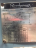
Now what I have up and running - I got 2 legs of the 3P 480V (they measure 480V between) and ran them 200ft to my transformer (see the pic above). I had my transformer's entry set up for 432V, so the secondary side is ~270V that goes into a 120/240V single phase breaker panel. I use this panel for the tesla charger, so I am not worried about "overvolting" other devices that require 120V or 240V. I use the center tap (X2 and X3) together with X1 and X2 to connect respectively N and L1 L2 on the panel. Bottom line - I have my HPWC connected to 268V and charging with 48A my Model 3. The DIP switches are set up to DOWN-UP as shipped from factory.

Pros and cons of both:
1) 1 leg of a 3P 480V (assuming this will work)
Pros: Less initial cost (no transformer), no power loss from the transformer
Cons: You need bigger (lower AWG) cables or the voltage drop will be significant.

2) 2 legs of 3P 480V with transformer
Pros: Lower gauge cables and you can install further away from your 480V panel
Cons: Cost of transformer, operational power loss in the transformer.

I only charged once in my current setup and can't provide numbers and stats yet, but my goal was to charge as fast as I can. Even if it cost more to install it.

Disclaimer: This is not a tutorial or anything like that. I share my experience and I am not liable for any damage you might cause.
 
It's about time for Wall Connector 3P (as in 3 phase) - hopefully the Y/truck/roadster will have a 3 phase charger built in...
At 48A per branch it will easily do 39kW. I am sure people will install 480V in their houses for a 2-3 hour full charging
 
X1-X4 should be 240v if the primary is connected according to the manufacturer's specification.

Sounds like you are intentionally connecting 480v to the primary as if it were 432v to get higher output voltage to X1-X4 to increase the charging rate of your car. Works as long as the transformer is dedicated to the car charging circuit. The center tap is not used for the wall connector.

Question: Why use the transformer at all? You could simply use the H1 or H4 feed and neutral to power the Wall Connector at 277v. No need for the tranformer, and you would charge even faster. It is explained in the manual. https://www.tesla.com/sites/default/files/80A_Wall_Connector_Installation_Manual_EN_JP_ES_0.pdf

upload_2018-12-10_21-0-48.png
 
Yeah, it looks like the Wall connector I got is a Gen II and the above is not in the manual.
The reason I went for a transformer is I have the 480V panel 200ft from where I wanted the connector installed. So I wanted to to reduce the voltage drop (using 480V instead of 277V) using the same 6AWG cable. Then wire the transformer for 432V and get 270V (263 when loaded with 48A). Which is what I did and accomplished my goal - to charge as fast as possible - 48*263=12,624W

At what price? This is where I made a mistake - I should have read more and used, as you suggested, one of the the 480Y277 legs directly. The transformer's consumption adds another 1kW (when connected at the 480V terminals) and 3kW when wired for 432V. Which is not that bad, but here comes the worse part - when not charging (non-load) these numbers are 2.5kW and whooping 10kW respectively for 480V and 432V. So now I only energize the transformer before charging and disconnect it after.

So bottom line - not only I spent a significant amount of money to buy and install the transformer, but now I am facing more losses from running it. I will rewire when I have more time and connect the Wall Connector straight to the 277V.

One thing I should mention though - this setup transformer is good for a second HPWC (and used simultaneously). If wire it directly - 6AWG can only take one HPWC

And I found another thread that is helpful, so here is the thread list on same same topic I read so far:

Info from Tesla - 277v feed to Wall Connector (HPWC) - Which Cars Support It
Charging Model 3 via HPWC - "Voltage Too High"
can charge on 277 volt AC? | Tesla
 
So I got that HPWC directly to the one leg of the 480V (278-280V). With the HPWC set to 48A I only get 47A. After voltage drop there are 270V applied to the car. So 270V*47A=12,690W looks to be the capacity of the Model 3 charger.
 
That is a good solution. I'd like to see the J-1772 standard updated to simply be 100-300v AC up to 80amps.

That way a J-1772 could also be connected directly to 3p480 service without the need for a transformer. Not sure of the history, but I think that is why lighting is 277v.

In the future I can see putting 12 HPWC (or 120 HPWC) in a parking lot on 3 100amp circuits (30 100 amp circuits). Would be nice to do the same with J-1772. The 12 HPWC would be just 4 wires (3 hots + common) and a ground.
 
Not sure about J-1772, but I couldn't catch the idea behind the 120 HPWC... I guess you could put up to 4HPWC on each leg and use load sharing my master/slave configuration. So these 4 could not go over the capacity of the 100A wire. 3 phases - total of 12 HPWC.
So I guess a 100A 3p480 circuit could power simultaneously 3 HPWC at max (80A). This only makes sense for S (and maybe X?), since 3's chargers are limited to 48A. But I also read that a lot of the S's chargers are very sensitive voltage wise and might not work with 270V and above.

On a side note I started thinking how would work "charging you car in 1min" as some manufacturers are claiming they are working on.
More in the other thread:
Claims for 1min EV charging time
 
Fast charging is DC. AC is for when you are parked for a while (overnight or at work are common).

12 HPWC on 3 circuits would be 80a available for every 4 - so 20a per if all in use (5.5kW), but if someone were alone they could pull the full 80a. 4 on one big circuit saves a lot of wiring and breakers over having a smaller dedicated circuit for each.

The 480v service reduces the wiring necessary. The 3 circuits on a 208/240 service would require 6 wires plus ground from the breaker panel. On 3p480v service it would require just 4 wires plus ground from the breaker panel. When wiring a parking lot with 120 connectors, that is a big savings.