This post is to share my experience installing a Gen 3 Wall Connector using MC 6/2 cable in the United States.
My install officially passed inspection yesterday. Though don't read too much into that; the inspection was rather superficial. I trust this forum to provide "constructive feedback" if they see anything concerning in this post.
DISCLAIMER: I am not an electrician, but I am permitted in my state to perform electrical work on a property which I both OWN and OCCUPY. I have previously worked with old BX cable, installed a transfer switch, added multiple new circuits, and extended multiple circuits. Though this is my first time working with wire larger than 12 gauge.
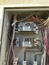
I hired a professional a few years ago to add a full 200 amp load center as a subpanel powered with feed through lugs from my overfull main 200 amp panel. Part of my reason for going so big was thinking that eventually I would want to add EVSE circuits. Since I have that almost empty 200 amp subpanel in my garage, adding this EVSE circuit was electrically simple.
In my opinion, figuring out which cable to use was the easy part. Page 5 of the Tesla Gen 3 Wall Connector Manual states: "If installing for maximum power, use minimum 6 AWG, 90 degree C-rated copper wire for conductors." As previously discussed in this thread, BOTH the "6 AWG" and the "90 degree C rating" are important. I wanted to pull my wire above the drywall ceiling in my garage, which is also under the floor of my master bedroom. Since I was pulling new wire anyway, I wanted to install for maximum power. So based on previous recommendations in this thread, I ended up purchasing 50' of MC cable from Wire and Cable Your Way.
Specifically I ordered: 6/2 Copper MC Cable w/ Ground
Full description:
- 6-2C Metal Clad (MC) Cable with Ground, Aluminum Armored, Stranded Copper Conductors
- Size 6 AWG
- Outside Diameter: 0.755 inches
- Ampere Rating THHN: 75 @ 90 degree C.
The cable actually arrived on a spool with an 8 awg label, which caused me to send pictures to customer support. Customer support responded that they would check with the factory. A week later customer support emailed that the factory says they sent 6 awg. At that point I stripped back enough of the cable to read the labels on the conductors. One conductor was labeled as 6 awg THHN and one as 6 awg THWN, so they did send 6/2 MC cable. The ground was stranded 8 awg.
If you enjoy cutting MC cable, keep using whatever technique you are already using. Otherwise, if you are installing the 6/2 cable that I used, definitely budget for a "Greenlee 0952-01 Quick Load Clamp Cable Cutter" (Amazon), or a more expensive equivalent. Once you adjust it with some test cuts, the basic technique is put the cable in the tool slot, pull the cable till it locks, turn the handle until the handle spins freely. Next remove the cable from the cutter, then grab the discard end with your favorite adjustable pliers and twist. After a few practice cuts you will easily strip the MC cable without damaging the insulation on the conductors. Besides saving time and cursing, the main advantage is that you can easily make repeated cuts without nicking the conductor insulation which increases safety.
Note: Wire and Cable Your Way did not include any red plastic anti-shorts. Technically I'm not sure anti-short bushings are required with MC. However, I wanted to protect my conductors. I ended up buying a package of 3/4" flex anti-short bushings at Home Depot. They turned out to be a bit too long, but with a little scissor trimming they did barely fit, and still made a full circle inside the MC. I don't know if trimming is to code. I am however confident the insulation on my conductors is well protected by what I did. It would obviously be much better if you could find anti-short bushings that actually fit without trimming.
The cable I ordered came with three wires, black, white, and green. So I picked up a roll of RED electrical tape at Home Depot. I wrapped the white wire with red tape before it went into the breaker, and before it went into the L2/N terminal block. That way the next electrician who looks at the marked white wire will instantly know it is being used as HOT not Neutral.
It was surprisingly difficult for me to find a connector rated for 0.755 inch aluminum MC cable. I found lots of Flexible Conduit connectors, but though they look very similar code does not automatically allow using them with MC cable. Eventually I found the "Arlington 8402 Cable Connector, AC/MC,3/4",Two Screw,Zinc Die Cast." I verified in the Arlington catalog that 0.755 inches was within the 8402's 0.525 - 0.780 cable size range. The table in the catalog also showed that the 8402 was rated for MC Aluminum Corrugated and MC Aluminum Contiguous Corrugated, as well as for options I knew I had not ordered including MC Steel, Armored Cable, and Flexible Metal Conduit. I used one connector for rear entry into the Wall Connector, and one at the load center.
I purchased my connectors through Rexelusa.com expecting to pick the order up locally, but they shipped it, and charged me nominal shipping. I did have to register to use their site. However, I listed my company as "Home Owner" and was quickly approved, unlike some other electrical supply houses. I have only used Rexel for that one order, so your mileage may vary.
Note: Both the cable and the 4802 connector I ordered are for DRY locations.
Some of you may also be interested in transitioning from MC to 3/4 inch EMT. Especially if you are feeding from the top or the bottom of the wall connector, and want to use a smooth EMT compression fitting for the final connection to the wall connector so the charging cable does not rub against rough objects like screws. An Arlington catalog explicitly showed screwing the 4802 connector into an "Arlington 2411 Zinc Combination Coupling; Fits 3/4 inch EMT - 3/4 inch F. Thread" to make that transition. I ordered one, and they do screw together. Thankfully, I did not end up needing to transition to EMT.
I was very fortunate that I was mounting my wall connector on a fairly deep box/wall that I had previously attached to my concrete garage wall when I installed a central vacumn and associated electrical outlets. It was tight, but the MC cable was just barely able to bend enough inside the deep box that I could feed the Wall Connector from the rear. Thus I did not need to transition to EMT to make a sharper bend, or to top feed the Wall Connector. I don't think the MC would have made the bend in a 2x4 stud wall, it MIGHT just barely in a 2x6 wall. but I think it would probably be fine in a 2x8 stud wall.
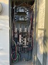
Ultimately, materials wise my install was very simple. The Gen 3 Wall Connector, an Arlington 4802 Cable Connector, an anti-short bushing, the 6/2 MC cable, another anti-short bushing, another Arlington 4802, and a simple 60 amp breaker that matched my load center. Supplemented with red tape to mark the white wire as hot, and some straps to secure the MC cable near the Load Center and Wall Connector. Straps are not required where I fished the cable through my ceiling.
I already owned most of the tools specified on page 12 of the Tesla installation manual. I purchased a torque screwdriver, aka torq driver, needed for tightening the wire connectors to the correct torque at the Wall Connector, the breaker, and the ground bar. The Wall Connector wants 50 pound-inches of torque, my breaker and ground bar specified twenty something pound-inches of torque (your breaker and ground bar may be different). I purchased a larger wire stripper capable of handling 6 awg and 8 awg stranded copper (the conductors are 6 awg, the ground is 8 awg). It is possible to strip wire without a wire stripper, and I initially planned to, but then I chickened out. The step bit specified was a bit pricy, but seemed required for rear entry. I'm very glad I also purchased a Greenlee 0952-01 cutter since I was using MC. I had to purchase a big auger bit to run the cable through a beam in the middle of my garage ceiling. I also purchased a fixed blade utility knife and a 50 pack of drywall blades for making holes in my ceiling. I already owned pull tape, fish rods, a big bolt cutter, a good wire cutter, wrenches, multi-screwdrivers, drill bits, multiple hand-drills, and (optional) a drill press.
Some suggestions (some gleaned from YouTube, some from personal mistakes):
- Read the Tesla installation manual at least twice.
- Get your conduit or MC cable connector location finalized before drilling pilot holes in the wall or the holes in the Wall Connector Wirebox. Then drill the Wirebox. Finally drill the pilot holes in the wall. Adjusting holes in the wall a fraction of an inch in any direction is easy. Adjusting the connector location is not always so easy. Tesla sells a replacement Wall Connector Wirebox Kit if you need to "adjust" something you did to the Wirebox.
- Thread the zip tie through the hole in the Wirebox before installing the wires. Then zip it after the wires are torqued down.
- Remember that the Wirebox and your breaker will both have strip gauges showing how much to strip the wire, and will also indicate how much torque they need (probably pound-INCHES). Not using ENOUGH torque is a common cause of fires. Using TOO MUCH torque can damage the connection. If you confuse pound-inches with pound-feet of torque you will break something.
- A Square Drive screwdriver is best for tightening most electrical screws these days. The Tesla Wirebox is an exception, and Tesla provides their own 4mm hex bit.
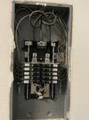
- Remember that the breaker and the ground bar in your load center might need different lengths of wire from the connector into the box. (Yes, I ended up installing a new ground bar in my subpanel.)
As I have previously posted, I have yet to view a single Wall Connector installation video on YouTube that didn't violate code somewhere. (My trimming of anti-short bushings might have continued the tradition in this post.) However, there are good videos by ELECTRICIANS on YouTube which can teach you some of the basics. I personally used:
Like most home projects, this one took longer than expected. I've cut into my garage ceiling before to install central vacumn piping and some 12 gauge circuits. Cutting into it where I had previously patched it was especially miserable. My blade also slipped and I blessed the project with my blood at one point when I cut through my glove, fingernail, and into the tip of a finger. If my garage ceiling was flat, I might have surface mounted EMT. However, I had to get past a plumbing chase which drops down in the middle anyway. Going above the drywall meant the resulting wires between the load center and the Wall Connector are completely concealed. Using MC meant the conductors are protected against future utility blades cutting drywall, and everything is rated for maximum Gen 3 power settings. I personally am very happy with the results; probably the Ikea affect.
If you don't feel totally confident working with electricity, but want to put some sweat equity in the job, then follow my rule
"Do not hire an electrician to do carpentry or drywall." In this context that means pull the MC cable yourself from your load center to where the charger is going, if necessary construct a place to mount the wall connector, and plan on repairing the holes you make yourself. Just hire an electrician to make the final connections at both ends, perhaps on an hourly basis.
My original load center is installed on a scrap of oriented strand board, which is mounted to two by fours attached to my garage's concrete walls. When I wanted a subpanel installed a few feet from my load center, I knew the electrician would need a similar setup to mount the subpanel. So I mounted pressure treated two by fours to the concrete wall. Then I mounted a sheet of plywood on the two by fours. I took me quite a few hours. I cursed some broken concrete drill bits, and had to go buy more. I probably overbuilt it, and I definitely built it for future expansion. However, when the electrician came to bid the subpanel installation he didn't have to charge me electrician rates for guessing how long it would take to drill holes in concrete.
Pulling cable is a miserable job full of uncertainties. In my case it required cutting multiple holes in the drywall ceiling, a bit of rerouting from my initial plan, and of course patching all those holes. My job only involved pulling cable from one side of a two car garage to the other side. I only used 36 feet of my 50 foot spool. Yet, it took me way more than eight hours just to pull the cable! No sane electrician is going to bid that job for less than thousands of dollars. However, just connecting the wires at both ends has almost no uncertainty, and most electricians could practically do that job in their sleep.
Good luck on your own project. Whether you do it yourself, hire some of it out, or hire it all out. At the end of the day I'm generally happy that I went Wall Connector, and totally happy that I went MC 6/2. Though I do wonder if I should have installed a J1772 charger and purchased a spare J1772 to Tesla adapter instead for future flexibility.