Yes, we were heading to court. He was going to lose his license.. They do NOT mess around. I spent 3 years trying to work with the contractor before I did. If need to, would not wait that long. It does not cost a penny to file.CSLB reports are pretty serious, so hopefully, the contractor works this out proactively.


Welcome to Tesla Motors Club
Discuss Tesla's Model S, Model 3, Model X, Model Y, Cybertruck, Roadster and More.
Register
Install the app
How to install the app on iOS
You can install our site as a web app on your iOS device by utilizing the Add to Home Screen feature in Safari. Please see this thread for more details on this.
Note: This feature may not be available in some browsers.
-
Want to remove ads? Register an account and login to see fewer ads, and become a Supporting Member to remove almost all ads.
You are using an out of date browser. It may not display this or other websites correctly.
You should upgrade or use an alternative browser.
You should upgrade or use an alternative browser.
Best plug type for EV charger?
- Thread starter h2ofun
- Start date
True but again, no one ever would have found this. For me it was pure luck, and I like understanding deals, AND, will to push when not rightWell you paid them to do the work to code. They screwed up. They should take this as a lesson to make sure they do things right, and in the future, they won't have to do the work over.
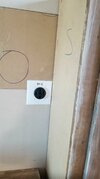
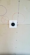
Okay, the electricans just left. We drove another 200 amp subpanel in my upper garage. We then wired up 5 EV charger
spots and put on 14-50 plugs for now.
I have to admit, pretty cool. NO way could I have added stuff later! It was all of it now, or never.
They found a neutral that is not the right size between panels so going to have to pay more to get that fixed right.
This stuff was sure not cheap, but,. .
Now if the leaf worked with v2h, as technically I read it should be able to.
wwhitney
Active Member
That's a bit unlikely (although certainly possible). The neutral needs to be at least as big as the minimum size EGC, but only as large as the calculated load on the neutral. Which can be a lot less than the ungrounded (hot) conductors if there are lots of 240V only loads.They found a neutral that is not the right size between panels so going to have to pay more to get that fixed right.
Anyway, if you want a second opinion, you can provide all the details.
Cheers, Wayne
Vines
Active Member
The neutral needs to be no smaller than the GEC right per 2017 NEC 250.102 and Table 250.102.C.1? Not the EGC per Table 250.122?That's a bit unlikely (although certainly possible). The neutral needs to be at least as big as the minimum size EGC, but only as large as the calculated load on the neutral. Which can be a lot less than the ungrounded (hot) conductors if there are lots of 240V only loads.
Anyway, if you want a second opinion, you can provide all the details.
Cheers, Wayne

wwhitney
Active Member
Let's see, 230.23(C) says a service grounded conductor (neutral) needs to be at least the size specified in 250.24(C), which references 250.120(C)(1), so correct for a service.The neutral needs to be no smaller than the GEC right per 2017 NEC 250.102 and Table 250.102.C.1? Not the EGC per Table 250.122?
But 215.2(A)(2) says a feeder grounded conductor must be no smaller than the EGC sized per Table 250.122.
Which is the usual dichotomy between before and after the service disconnect. I assumed a feeder was under discussion (as implied by my reference to the EGC, which does not exist before the service disconnect).
Cheers, Wayne
Vines
Active Member
Thank You Wayne, I think some of the PV people get wild thinking that the PV source is like a utility service source. I am glad to be on the path of learning the code more in depth.Let's see, 230.23(C) says a service grounded conductor (neutral) needs to be at least the size specified in 250.24(C), which references 250.120(C)(1), so correct for a service.
But 215.2(A)(2) says a feeder grounded conductor must be no smaller than the EGC sized per Table 250.122.
Which is the usual dichotomy between before and after the service disconnect. I assumed a feeder was under discussion (as implied by my reference to the EGC, which does not exist before the service disconnect).
Cheers, Wayne
I believe it was aluminum and too small, so he will replace with copper 3. I just this guy knows his stuff, so I would rather pay him 800 bucksLet's see, 230.23(C) says a service grounded conductor (neutral) needs to be at least the size specified in 250.24(C), which references 250.120(C)(1), so correct for a service.
But 215.2(A)(2) says a feeder grounded conductor must be no smaller than the EGC sized per Table 250.122.
Which is the usual dichotomy between before and after the service disconnect. I assumed a feeder was under discussion (as implied by my reference to the EGC, which does not exist before the service disconnect).
Cheers, Wayne
to "fix", and let him know I really thank him for pointing it out. Most folks would have ignored since they would not want to fix
others issues!!
I also had to install these charges, meaning the new sub panel, ahead of the gateway. Was just no way to get the huge wiring connected
post GW. I guess I now have some non backed up loads. Would one really need to charge an EV if power is out, technically maybe, practically probably never.
wwhitney
Active Member
Maximum allowable OCPD (breaker) for a 14-50 receptacle is 50A.Glad I had them put on 14-50 plugs so a charger can be plugged in
Cheers, Wayne
That makes sense.Maximum allowable OCPD (breaker) for a 14-50 receptacle is 50A.
Cheers, Wayne
We went with 90C #6 wire in metal flex, so that technically is good for 70 amps from what I see.
But if I were to put in a tesla
gen 3 charger, are these an issues using a 70 amp breaker, or do they have to be 60 amp?
Vines
Active Member
What he is saying is that you cannot put a NEMA 14-50 receptacle at the end of that 70A circuit, even if later you plan to remove the outlet and install a HPWC. Same goes if you plan to plug in a HPWC to that outlet (assuming you can still get a HPWC with a NEMA 14-50 plug)That makes sense.
We went with 90C #6 wire in metal flex, so that technically is good for 70 amps from what I see.
But if I were to put in a tesla
gen 3 charger, are these an issues using a 70 amp breaker, or do they have to be 60 amp?
I believe GEN 2 HPWC could take a 70A circuit, but I think the GEN 3 max out at 60A circuits.
Also, if that is #6 wire the maximum ampacity that circuit could be is 65A, since the equipment on either side certainly has 75 degree terminals, which limits the circuit ampacity, despite the wire alone being suitable for 75A at 90C.
Am I the only one slightly concerned that the is an (unlicensed?) "electrician" out there who doesn't know that?Maximum allowable OCPD (breaker) for a 14-50 receptacle is 50A.
Cheers, Wayne
wwhitney
Active Member
So as long as you have the 14-50 receptacle in the circuit, you need to reduce the OCPD down to 50A. Which will likely create a 250.122(B) violation (what size EGC and neutral was run?), although that's minor.That makes sense.
As I've posted before (in this thread?) you basically never achieve the full 90C rating of conductors in practice (75A for #6 Cu). So you'll be limited to the 75C rating of 65A.We went with 90C #6 wire in metal flex, so that technically is good for 70 amps from what I see.
Looking through the Gen 3 TWC manual, the max output is 48A continuous, so a 60A branch circuit would be sufficient. I don't see it explicitly saying "60A maximum" anywhere (could have missed it), but 60A is referred to often and would be the obvious choice.But if I were to put in a tesla gen 3 charger, are these an issues using a 70 amp breaker, or do they have to be 60 amp?
Also, what are the feeder conductors and method for the 200A subpanel, and what OCPD is protecting those conductors? You won't be able to install more than (3) TWC set at 48A unless you enable their load sharing feature to limit the total current to 160A (assuming a 200A feeder is supplying your 200A main breaker subpanel).
Lastly, given the above issues with our latest work, I suggest you get a second opinion on replacing that neutral. Where is it, what size is it, what OCPD is at the supply end, and what loads does it carry?
Cheers, Wayne
Neutral and hots are all #6 awg. Looks like gnd was smaller.So as long as you have the 14-50 receptacle in the circuit, you need to reduce the OCPD down to 50A. Which will likely create a 250.122(B) violation (what size EGC and neutral was run?), although that's minor.
As I've posted before (in this thread?) you basically never achieve the full 90C rating of conductors in practice (75A for #6 Cu). So you'll be limited to the 75C rating of 65A.
Looking through the Gen 3 TWC manual, the max output is 48A continuous, so a 60A branch circuit would be sufficient. I don't see it explicitly saying "60A maximum" anywhere (could have missed it), but 60A is referred to often and would be the obvious choice.
Also, what are the feeder conductors and method for the 200A subpanel, and what OCPD is protecting those conductors? You won't be able to install more than (3) TWC set at 48A unless you enable their load sharing feature to limit the total current to 160A (assuming a 200A feeder is supplying your 200A main breaker subpanel).
Lastly, given the above issues with our latest work, I suggest you get a second opinion on replacing that neutral. Where is it, what size is it, what OCPD is at the supply end, and what loads does it carry?
Cheers, Wayne
He said reason he did not get 60 amp is they were out. I just wrote him saying I need 50 amp breakers with the 14-50 plugs. Need 60 amp if
I go with something hardwired like the Tesla Gen 3. At least my wiring gives me flexibility to go to 70 amp breakers if needed.
The wiring I believe was called #2/0 NM, it is the largest stuff I have seen, copper, which goes everywhere.
These stuff is protected by the 200 amp breaker in the main service panel.
I assume if I were, which will never happen, I would install 5 gen 3 and use load sharing since yep, got to limit, and 160 continuous amps is still nuts, and expensive.
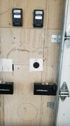
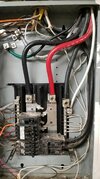
I forget the size of the neutral in the one subpanel he said. Much smaller than the feeds. Picture attached
Attachments
wwhitney
Active Member
With 75C (i.e. not NM) Cu #6 ungrounded (hot) conductors:Neutral and hots are all #6 awg. Looks like gnd was smaller.
70A OCPD --good for loads up to 65A only--#8 Cu EGC
60A OCPD--#10 Cu EGC
50A OCPD--#8 Cu EGC (*)
[I don't make the rules, but yes, if you downsize the OCPD from 60A to 50A you are supposed to upsize the EGC.]
(*) Unless #8 ungrounded conductors wouldn't be large enough due to derating for temperature or number of current carrying conductors.
NM cable maxes out at #2 Cu, which is only good for 95A.The wiring I believe was called #2/0 NM, it is the largest stuff I have seen, copper, which goes everywhere.
These stuff is protected by the 200 amp breaker in the main service panel.
Is your main service 200A only, not a 400A service with dual 200A disconnects? If so, then 2/0 Cu is sufficient for protection at 200A, and I'd say OK for 160A continuous (although it's arguably a grey area and could be construed to be limited to 140A continuous). Or 4/0 Al (same grey area, possibly only good for 144A continuous).
If it is a 400A (2x200A) service, then you would need 3/0 Cu, 2/0 Cu is too small and would require a 175A breaker. In Al you could still use 4/0, but it would be unambiguously limited to 180A of load, or 144A continuous.
Cheers,
Wayne
The large white wire in that photo is connected to your neutral bar but is not part of the supply to that panel. The supply are the fat black, red, and black with grey stripe Aluminum conductors.I forget the size of the neutral in the one subpanel he said. Much smaller than the feeds. Picture attached
I'd need to know more about which wires are exiting each of the top two large holes at the top, and where they are going, but my first guess is that the white wire is associated with the two black wires on the 100A breaker at the bottom. In which case it is going out the wrong hole in the panel, it should exit via the same hole as the associated ungrounded (hot) conductors.
Of course that theory only makes sense if both of those holes go to the same enclosure. And the fact the 100A exit through the same hole as some NM
cables is a bit unusual, would be interested to see what is going on just above the panel.
BTW, if your electrician actually said to you "the white wire is too small compared to the big red wire" then they are pretty clueless about what they are looking at. If they said "the white wire is going out the wrong hole" that's correct. If they said "the white wire is too small compared to the wires on the 100A breaker" then that may or may not be true and would require a load calculation to decide.
Cheers, Wayne
Last edited:
cobra
Member
Did you notice, it appears there is a third smaller black wire behind the lower of the two blacks on the 100A. Looks like it is possibly running behind the two 100A conductors, but hard to tell. May be the associated 3rd wire for the 100A circuit? (It's shadowed too, at the bottom, some might not be black either.) Doesn't help explain what the white is though, as I see why you think the white may be associated with the 100A pair.The large white wire in that photo is connected to your neutral bar but is not part of the supply to that panel. The supply are the fat black, red, and black with grey stripe Aluminum conductors.
I'd need to know more about which wires are exiting each of the top two large holes at the top, and where they are going, but my first guess is that the white wire is associated with the two black wires on the 100A breaker at the bottom. In which case it is going out the wrong hole in the panel, it should exit via the same hole as the associated ungrounded (hot) conductors.
Of course that theory only makes sense if both of those holes go to the same enclosure. And the fact the 100A exit through the same hole as some NM
cables is a bit unusual, would be interested to see what is going on just above the panel.
Not sure about your 400 am comments. I have a 400 amp service from PGE going into the meter box. This meter box has 2 200 amp breakers in it.With 75C (i.e. not NM) Cu #6 ungrounded (hot) conductors:
70A OCPD --good for loads up to 65A only--#8 Cu EGC
60A OCPD--#10 Cu EGC
50A OCPD--#8 Cu EGC (*)
[I don't make the rules, but yes, if you downsize the OCPD from 60A to 50A you are supposed to upsize the EGC.]
(*) Unless #8 ungrounded conductors wouldn't be large enough due to derating for temperature or number of current carrying conductors.
NM cable maxes out at #2 Cu, which is only good for 95A.
Is your main service 200A only, not a 400A service with dual 200A disconnects? If so, then 2/0 Cu is sufficient for protection at 200A, and I'd say OK for 160A continuous (although it's arguably a grey area and could be construed to be limited to 140A continuous). Or 4/0 Al (same grey area, possibly only good for 144A continuous).
If it is a 400A (2x200A) service, then you would need 3/0 Cu, 2/0 Cu is too small and would require a 175A breaker. In Al you could still use 4/0, but it would be unambiguously limited to 180A of load, or 144A continuous.
Cheers,
Wayne
The large white wire in that photo is connected to your neutral bar but is not part of the supply to that panel. The supply are the fat black, red, and black with grey stripe Aluminum conductors.
I'd need to know more about which wires are exiting each of the top two large holes at the top, and where they are going, but my first guess is that the white wire is associated with the two black wires on the 100A breaker at the bottom. In which case it is going out the wrong hole in the panel, it should exit via the same hole as the associated ungrounded (hot) conductors.
Of course that theory only makes sense if both of those holes go to the same enclosure. And the fact the 100A exit through the same hole as some NM
cables is a bit unusual, would be interested to see what is going on just above the panel.
BTW, if your electrician actually said to you "the white wire is too small compared to the big red wire" then they are pretty clueless about what they are looking at. If they said "the white wire is going out the wrong hole" that's correct. If they said "the white wire is too small compared to the wires on the 100A breaker" then that may or may not be true and would require a load calculation to decide.
Cheers, Wayne
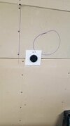
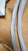
Wire looks aluminum? Is this sized correctly?
Attachments
wwhitney
Active Member
That's 4/0 - 4/0 - 4/0 - 2/0 Aluminum SER cable. 4/0 Al has a 75C ampacity of 180A. So your supply is basically 2 x 180A. The calculated load on either side is limited to 180A. [If the service conductors (upstream of the meter) are smaller than 300A in base ampacity, then there's a further limit to the combined load on both sides.] That's all fine.Not sure about your 400 am comments. I have a 400 amp service from PGE going into the meter box. This meter box has 2 200 amp breakers in it.
Wire looks aluminum? Is this sized correctly?
However, that means if your electrician ran any 2/0 Cu that is protected at 200A, it's a violation. 2/0 Cu is limited to 175A almost always, including here. [Also, running Cu instead of Al for large feeders is generally a waste of money with no particular upside.]
The backstory, and source of confusion, is that the NEC has a special allowance for residential services, along with main feeders that carry all the loads of a dwelling unit. It says that after everything else, you get to apply an 83% factor in sizing the conductors. It also says any wires downstream needn't be any larger than the service/main feeder conductors.
So for a 200A residential service, you only need to supply conductors with a 166A ampacity. That means 4/0 Al (75C ampacity 180A) or 2/0 Cu (75C ampacity 175A) is sufficient to provide a full 200A service.
However, on a larger residential service, the 83% rule doesn't apply to a 200A feeder. 4/0 Al can still be protected at 200A under the "next size up" rule, as 180A is not a standard breaker size, as long as the load is 180A or less. But 175A is a standard breaker size, so 2/0 Cu needs to be protected at 175A (when not on a 200A residential service).
[Also 180 * 2 * 83% = 300A, the source of that earlier figure.]
Cheers, Wayne
Similar threads
- Replies
- 32
- Views
- 1K
- Question
- Replies
- 16
- Views
- 1K
- Replies
- 5
- Views
- 307
- Replies
- 9
- Views
- 666