


Welcome to Tesla Motors Club
Discuss Tesla's Model S, Model 3, Model X, Model Y, Cybertruck, Roadster and More.
Register
Install the app
How to install the app on iOS
You can install our site as a web app on your iOS device by utilizing the Add to Home Screen feature in Safari. Please see this thread for more details on this.
Note: This feature may not be available in some browsers.
-
Want to remove ads? Register an account and login to see fewer ads, and become a Supporting Member to remove almost all ads.
You are using an out of date browser. It may not display this or other websites correctly.
You should upgrade or use an alternative browser.
You should upgrade or use an alternative browser.
- Status
- Not open for further replies.
RFICDude
Member
@davitsio any update on how the 8" adapter prototype is working out?
Also, the male connector for the 4" speakers apparently is available as a stand alone connector which would help with making speaker connector cables without 3D printing the housing. A person on, another forum, posted a connector housing part number 1-1534155-1 which is available from most electronic distributors ( Digikey, Mouser and Arrow). I can't tell for sure if the actual crimp pins come with the housing or if you must order them separately.
They are pretty cheap, so I'll order some.
I'm also placing an order for your 4" brackets (thanks).
Hello, All! Yes, update on the woofers. Good and Bad news. The good news is that I took the door apart again and tested the prototype out, and most of it is exactly right. The bad news is that there is one problem that I do not know if I can fix without rebuilding the bracket from the ground up. Here's the deal:
The screwholes, the base, and the depth all fit. I will need to add some cutouts for each screw as the width of the bracket is just a little too much to fit the (flanges?) on the head of the screw. That's easy enough, though. The depth works!! That's good news as that was what I was most worried about. It will fit under the door (barely) without the magnet hitting the frame. The bad news.... The width of the bracket is just a little too much on the very bottom for the door trim panel to slide over. I know how this can be fixed mechanically, but I literally taught myself 3D modeling for this project, and and I am not sure I actually have the needed skills to make those modifications in my modeling software. I will try to shorten the depth another couple millimeters, as this will slightly assuage that problem--perhaps enough to make it work. But I really am not certain. Honestly, this is pretty disappointing for me with all the work I put into it so far.
Does anyone out there have more advanced modeling skills than I have? I know exactly what needs done, just not how to do it. I will do the shortening I mentioned earlier and make the cutouts. If that works, then we're done. If it doesn't, I may not have the skills needed to make the required shape change of the bracket cylinder. Ironically, this confirms that the speaker will indeed fit in depth. It's the width that is causing issues!
Any thoughts? Here are photos of the bracket as I tested it today. I printed it off in two pieces and used plastic epoxy to bond them. It's really working perfectly except for that one width issue I mentioned.
Last edited:
@davitsio any update on how the 8" adapter prototype is working out?
Also, the male connector for the 4" speakers apparently is available as a stand alone connector which would help with making speaker connector cables without 3D printing the housing. A person on, another forum, posted a connector housing part number 1-1534155-1 which is available from most electronic distributors ( Digikey, Mouser and Arrow). I can't tell for sure if the actual crimp pins come with the housing or if you must order them separately.
They are pretty cheap, so I'll order some.
I'm also placing an order for your 4" brackets (thanks).
That's great news. Honestly, I hate making the cables lol. The soldering is really awkward will all that delicate plastic around, since I don't have a proper "workshop". so I am hopeful that this will provide a better alternative. The brackets are mostly just printer work, so that's something I don't mind doing. Thanks for ordering and let me know if you have any trouble with the install or any questions!
I will make one recommendation for you, and for everyone else who has ordered. I have come to realize over a month or two that the screws holding the midrange speakers in place will vibrate loose over time. I will add lock washers to the install when I get around to it, and I suggest you do the same. I don't know why the stock speakers didn't have this issue, I imagine they must have been every so slightly adhered in place somehow. But my screws are slowly loosening now that I have made the speaker swap. Home Depot should have the necessary lock washers.
One other note: The focal tweeters make a big difference, by the way, if you are feeling adventurous. Mine are now sounding just perfect. For whatever reason they needed a couple weeks to "break-in" and now the harshness is gone.
RFICDude
Member
Awesome work @davitsio on the prototype especially for a project where you are learning 3D modeling.
I have a question to help clarify the issue you are having.
Is the problem the width of the cylinder, that the speaker sits on, at the bottom where the cylinder meets the bracket that bolts to the door?
If this is the issue, would making the diameter (width) of the cyclinder narrower at the bottom fix the problem?
Or is the problem a different dimension?
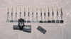
BTW, I included a picture of the connectors which arrived just a few days after your brackets (Thanks!). I'm all set to swap out the three front midrange speakers.
I have a question to help clarify the issue you are having.
Is the problem the width of the cylinder, that the speaker sits on, at the bottom where the cylinder meets the bracket that bolts to the door?
If this is the issue, would making the diameter (width) of the cyclinder narrower at the bottom fix the problem?
Or is the problem a different dimension?
BTW, I included a picture of the connectors which arrived just a few days after your brackets (Thanks!). I'm all set to swap out the three front midrange speakers.
Attachments
Thanks!Is the problem the width of the cylinder, that the speaker sits on, at the bottom where the cylinder meets the bracket that bolts to the door?
If this is the issue, would making the diameter (width) of the cyclinder narrower at the bottom fix the problem?
The problem is indeed the bottom of the cylinder. So your solution is correct. I believe that taking the cylinder and narrowing it toward the bottom and middle, and then expanding toward the speaker itself, is the correct way to go. The problem is that, I believe, that involves a technique known as lofting, and that is something I do not know how to do. The lofting is needed because the cylinder has to be wide where it meets the base, and also where it meets the speaker (kind of like a slight hourglass-effect)I have no doubt I could learn it, but the struggle is about how much time I have to spend on these side projects. If you have some knowledge there, (or anyone else) I could use the assistance!
However, since all the other dimensions are right, I believe that narrowing the cylinder will complete the project.
groovyd
Member
Thanks!
The problem is indeed the bottom of the cylinder. So your solution is correct. I believe that taking the cylinder and narrowing it toward the bottom and middle, and then expanding toward the speaker itself, is the correct way to go. The problem is that, I believe, that involves a technique known as lofting, and that is something I do not know how to do. The lofting is needed because the cylinder has to be wide where it meets the base, and also where it meets the speaker (kind of like a slight hourglass-effect)I have no doubt I could learn it, but the struggle is about how much time I have to spend on these side projects. If you have some knowledge there, (or anyone else) I could use the assistance!
However, since all the other dimensions are right, I believe that narrowing the cylinder will complete the project.
Im not a CAD expert but I have a friend who is. If you email me or post the exact CAD files somewhere I can download them from and another sketch of exactly what you think needs done I can forward it to my friend who might be able to help.
RFICDude
Member
Here are a few direct links to multiple distributors for the 4" speaker connectors.
Male connector housing (same as what is on the speaker)
TE Connectivity 1-1534155-1
1-1534155-1 TE Connectivity / AMP | Mouser
https://www.digikey.com/products/en?WT.z_se_ps=1&keywords=1-1534155-1
PINs (I used gold but there are other numbers for tin)
TE Connectivity 963716-2
963716-2 TE Connectivity / AMP | Mouser
Looks like Digikey doesn't have the gold pin in stock right now, but they do have the regular pin
963716-1 TE Connectivity AMP Connectors | Connectors, Interconnects | DigiKey
There is also a "retainer" which I think is just a cap to cover up the two holes where the barb on the pin locks the pin into the housing.
It doesn't appear to be necessary to make the connector work, but I ordered some anyway.
1534027-1 TE Connectivity / AMP | Mouser
https://www.digikey.com/products/en?keywords=1534027-1
I'm not versed in 3D modeling, but I'm technically inclined. One way to generate the cylinder with different diameters is to use a cone with the top cut off at the needed diameter and height. However, I don't know if the software uses this approach to generating a geometry. I'll dig a little, but someone more experienced will probably come up with a quicker solution.
flashflooder
Member
Here are a few direct links to multiple distributors for the 4" speaker connectors.
Male connector housing (same as what is on the speaker)
TE Connectivity 1-1534155-1
1-1534155-1 TE Connectivity / AMP | Mouser
https://www.digikey.com/products/en?WT.z_se_ps=1&keywords=1-1534155-1
PINs (I used gold but there are other numbers for tin)
TE Connectivity 963716-2
963716-2 TE Connectivity / AMP | Mouser
Looks like Digikey doesn't have the gold pin in stock right now, but they do have the regular pin
963716-1 TE Connectivity AMP Connectors | Connectors, Interconnects | DigiKey
There is also a "retainer" which I think is just a cap to cover up the two holes where the barb on the pin locks the pin into the housing.
It doesn't appear to be necessary to make the connector work, but I ordered some anyway.
1534027-1 TE Connectivity / AMP | Mouser
https://www.digikey.com/products/en?keywords=1534027-1
I'm not versed in 3D modeling, but I'm technically inclined. One way to generate the cylinder with different diameters is to use a cone with the top cut off at the needed diameter and height. However, I don't know if the software uses this approach to generating a geometry. I'll dig a little, but someone more experienced will probably come up with a quicker solution.
unfortunately, designing a bracket that's going to work is much, much harder than just cutting the top and bottom off a cone. The geometry is irregular in more than one dimension.
Also, as promised, here is the STL for the prototype woofer bracket for the ISU-200.
Did anyone tried this bracket yet? or is anyone about to do so? Since I won't be working on this for another ~4-5 weeks, I'm willing to put in cash for someone to try this. The cash would be to compensate any lost to return the speaker to the vendor (re-stocking fee? shipping fee? etc).
For those who haven't noticed... when buying a pair of ISU-200, it includes a pair of Focal TWU 1.5 tweeters.
Replying to my own message
I just spotted a message from @davitsio - the bracket needs slight adjustment... I wonder if the current 3d bracket can be used as-is with some "grinding" and perhaps some ... glue. Of course I'd rather not having to do this.
I will make one recommendation for you, and for everyone else who has ordered. I have come to realize over a month or two that the screws holding the midrange speakers in place will vibrate loose over time. I will add lock washers to the install when I get around to it, and I suggest you do the same.
.
Ask your girlfriend for transparent nail polish to apply on the screw. Not sure if it dries as fast as loctite, perhaps not as strong, but should hold on.
Hello, all! I have finally gotten back to things after the holidays and have learned some lofting and a bit more skill in 3D modeling in general. So, I have updated the model with all the modifcations that I wrote down when I last tested the brackets and so have yet another prototype iteration to test. The weather in Boston right now is -4C, so too cold to test these without a garage, but if anyone want to test them, I'd be happy to ship over a bracket. I will get around to testing them eventually, but probably not until the weather warms. I am printing the braket in two pieces and using epoxy to bond them. This is much easier than trying to print in one huge piece with supports everywhere.
As a reminder to everyone, you can order printed brackets from me if you want at www.audioliphe.com . I will not be building cables for people anymore because it's a huge pain, but I will be happy to let everyone know how I build them so you can do it yourself, and maybe I will sell a kit to do that in the near future, as one creative forum member suggested.
Here's some photos of the brackets. The files I am uploading here are the STL for the new brackets (in case someone has a 3D printer and wants to try). I also have the Fusion 360 file as well and can post it if someone wants to tweak it. I am releasing all of this in the Creative Commons Attributon-NonCommercial-ShareAlike license, which means you can do whatever you want with it as long as you don't sell the brackets as a business and you share whatever modifications you make with the community as well.
Attachments
groovyd
Member
Hello, all! I have finally gotten back to things after the holidays and have learned some lofting and a bit more skill in 3D modeling in general. So, I have updated the model with all the modifcations that I wrote down when I last tested the brackets and so have yet another prototype iteration to test. The weather in Boston right now is -4C, so too cold to test these without a garage, but if anyone want to test them, I'd be happy to ship over a bracket. I will get around to testing them eventually, but probably not until the weather warms. I am printing the braket in two pieces and using epoxy to bond them. This is much easier than trying to print in one huge piece with supports everywhere.
As a reminder to everyone, you can order printed brackets from me if you want at www.audioliphe.com . I will not be building cables for people anymore because it's a huge pain, but I will be happy to let everyone know how I build them so you can do it yourself, and maybe I will sell a kit to do that in the near future, as one creative forum member suggested.
Here's some photos of the brackets. The files I am uploading here are the STL for the new brackets (in case someone has a 3D printer and wants to try). I also have the Fusion 360 file as well and can post it if someone wants to tweak it. I am releasing all of this in the Creative Commons Attributon-NonCommercial-ShareAlike license, which means you can do whatever you want with it as long as you don't sell the brackets as a business and you share whatever modifications you make with the community as well. View attachment 498489 View attachment 498481 View attachment 498483 View attachment 498484 View attachment 498485
I'm waiting for summer to before taking on this project and will wait to make sure you got all the changes to make it right the first time. No interest digging into the doors twice. Let us know when everything is perfect and i'll place my order.
Hello!
Good news, I have received all speakers... tweeter, mid & woofer. I had the tweeter/mid brackets printed via online service in December, so I'm missing the woofer ones and planning to order today / tomorrow. I'm a bit clueless at 3d printing, got a quote for PETG @ 20% infill @ ~55$. Is 20% enough for such this woofer or should I do 40% to make sure nothing falls apart?
Good news, I have received all speakers... tweeter, mid & woofer. I had the tweeter/mid brackets printed via online service in December, so I'm missing the woofer ones and planning to order today / tomorrow. I'm a bit clueless at 3d printing, got a quote for PETG @ 20% infill @ ~55$. Is 20% enough for such this woofer or should I do 40% to make sure nothing falls apart?
I can't find that information, is the connector for the woofer the same as the mid one? I received my Digikey order for the 5 mid connectors but ... I forgot about the woofer.
@davitsio let me know if your offer to ship a bracket kit is still available, I can provide you the shipping label and once tested, I can ship back. I'm doing sound deadening (floor, trunk, all doors) - at very part time - it will likely take me another ~3-4 weeks before due to life keeping me too busy
@davitsio let me know if your offer to ship a bracket kit is still available, I can provide you the shipping label and once tested, I can ship back. I'm doing sound deadening (floor, trunk, all doors) - at very part time - it will likely take me another ~3-4 weeks before due to life keeping me too busy
Replacement of the OEM front 3 tweeters & 3 mids is now complete.
The most difficult part was to built the cables for the tweeters. Even with years of experience with a solder, it was a challenge. The idea is to solder the wire to a pin header strip without melting the plastic. The easiest way I found is to secure the pins of the strip in a bench vise. That secures everything in place even when the plastic reaches melting temperature. Sadly I don't have a bench vise, I improvised using another tool that has a "flat head".
I couldn't find in this thread the type of header pin strip, this works and you have plenty of pins to practice your soldering technique https://www.amazon.com/gp/product/B00UVPT5RI
Next step will be front and root door speakers but I'm missing the connectors and brackets. I need to remove the door panel and validate the connector type, etc. The front door brakets are expensive to print via online service, I might wait for someone with a 3d printer to try the latest version.
The most difficult part was to built the cables for the tweeters. Even with years of experience with a solder, it was a challenge. The idea is to solder the wire to a pin header strip without melting the plastic. The easiest way I found is to secure the pins of the strip in a bench vise. That secures everything in place even when the plastic reaches melting temperature. Sadly I don't have a bench vise, I improvised using another tool that has a "flat head".
I couldn't find in this thread the type of header pin strip, this works and you have plenty of pins to practice your soldering technique
https://www.amazon.com/gp/product/B00UVPT5RINext step will be front and root door speakers but I'm missing the connectors and brackets. I need to remove the door panel and validate the connector type, etc. The front door brakets are expensive to print via online service, I might wait for someone with a 3d printer to try the latest version.
Last edited:
Hello, all! I have finally gotten back to things after the holidays and have learned some lofting and a bit more skill in 3D modeling in general. So, I have updated the model with all the modifcations that I wrote down when I last tested the brackets and so have yet another prototype iteration to test. The weather in Boston right now is -4C, so too cold to test these without a garage, but if anyone want to test them, I'd be happy to ship over a bracket. I will get around to testing them eventually, but probably not until the weather warms. I am printing the braket in two pieces and using epoxy to bond them. This is much easier than trying to print in one huge piece with supports everywhere.
As a reminder to everyone, you can order printed brackets from me if you want at www.audioliphe.com . I will not be building cables for people anymore because it's a huge pain, but I will be happy to let everyone know how I build them so you can do it yourself, and maybe I will sell a kit to do that in the near future, as one creative forum member suggested.
Here's some photos of the brackets. The files I am uploading here are the STL for the new brackets (in case someone has a 3D printer and wants to try). I also have the Fusion 360 file as well and can post it if someone wants to tweak it. I am releasing all of this in the Creative Commons Attributon-NonCommercial-ShareAlike license, which means you can do whatever you want with it as long as you don't sell the brackets as a business and you share whatever modifications you make with the community as well. View attachment 498489 View attachment 498481 View attachment 498483 View attachment 498484 View attachment 498485
@davitsio Just want to confirm that im right in saying that the above brackets are for the Front door woofers? and also for the Focal ISU200 speakers?
Appricate all the hard work you have put into this. The videos are a HUGE help and the stl files are a massive bonus.
Also i am using a different 4inch speaker due to the Infinity 4032 not being available in the UK or Europe! so had to do some detective work to match the sizes etc. I will mention which speakers i used once i have installed them so no one gets burnt if it does not work/fit going off what i bought!
- Status
- Not open for further replies.
Similar threads
- Replies
- 102
- Views
- 6K
- Replies
- 1
- Views
- 2K
- Replies
- 4
- Views
- 3K
- Replies
- 30
- Views
- 3K
- Replies
- 18
- Views
- 3K