


Picked up a CHAdeMO adapter earlier today to tear apart for an upcoming project.
Probably one of the most annoying things I've ever taken apart. The housing was put together with the board and wiring and all, then injected with rubber potting material. So nearly 100% of the innards were imprisoned inside solid rubber. Awesome for the design, terrible for me.
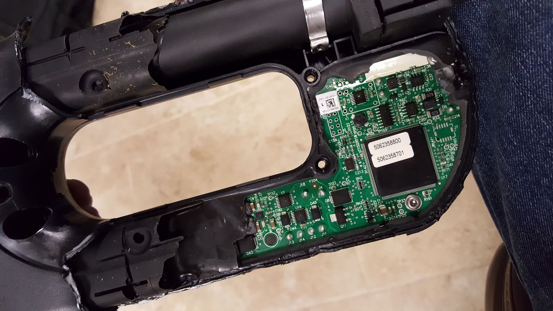
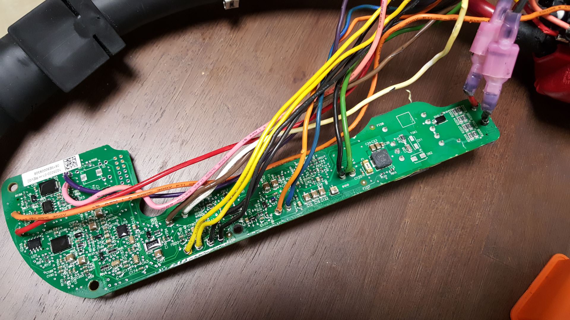
Here is a shot after I finally removed some of the rubber that was on top of the PCB portion.
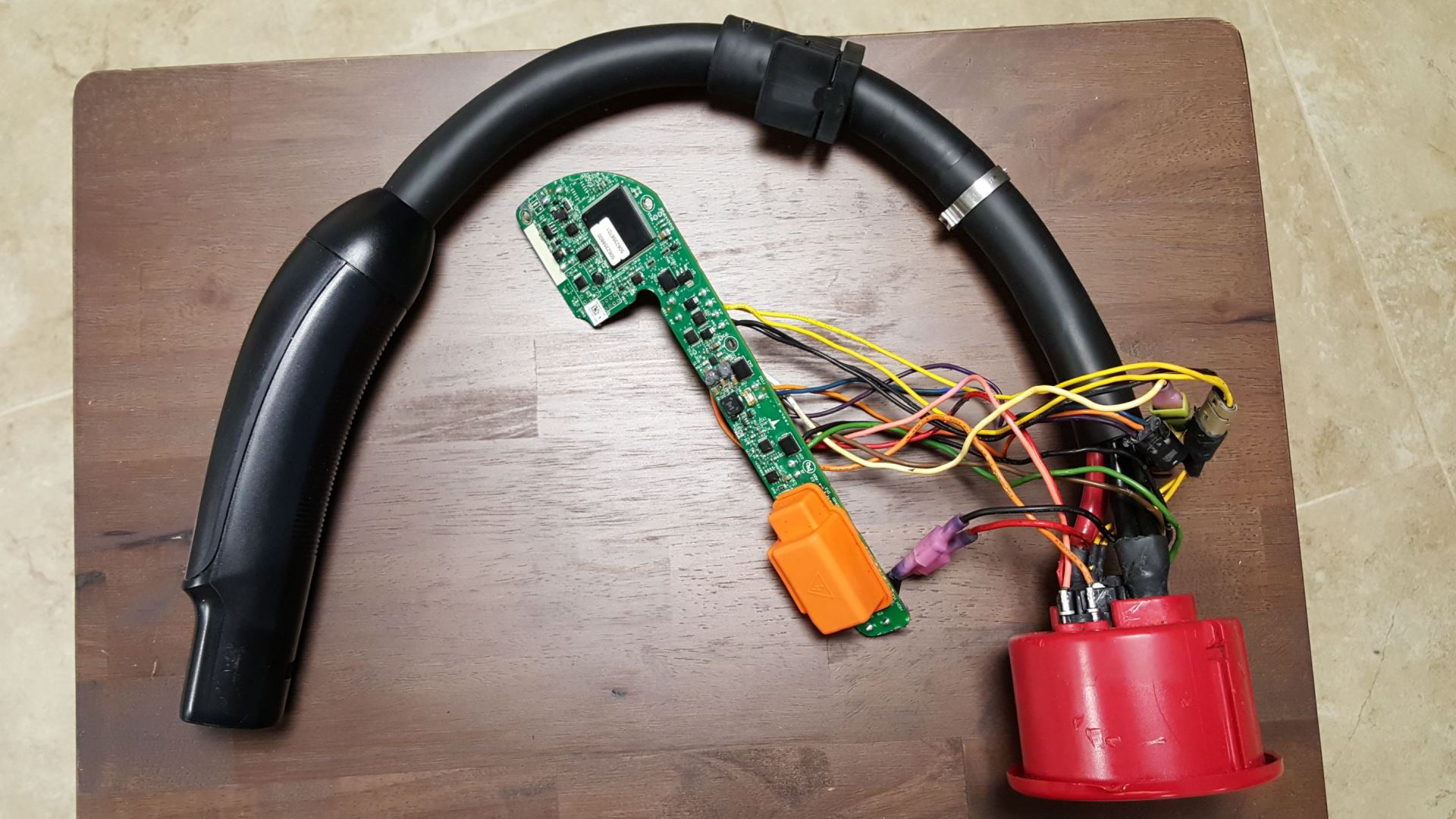
Working off and on at it over several hours picking at the rubber trying not to damage the board I finally was able to free it. I caused some damage to the low voltage wiring while trying to free everything from its rubber prison, but, not an issue since I won't be using it as it is for my upcoming project.
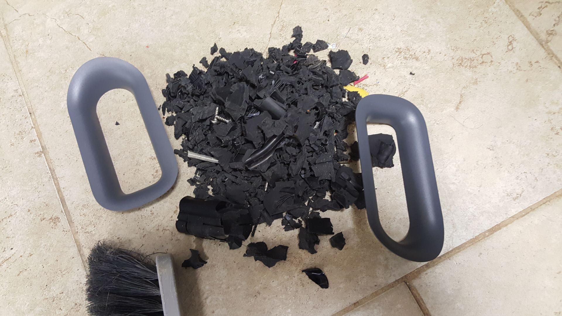
All of the rubber pieces I pulled out of the thing swept up... definitely a pain.
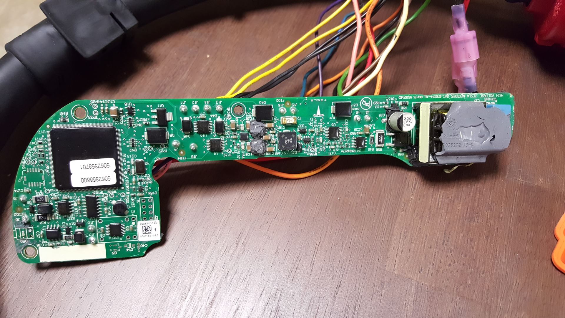
Here are some shots of the PCB front and back. Click for very high resolution versions.
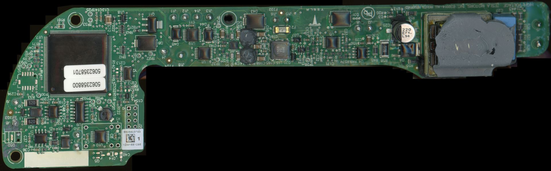
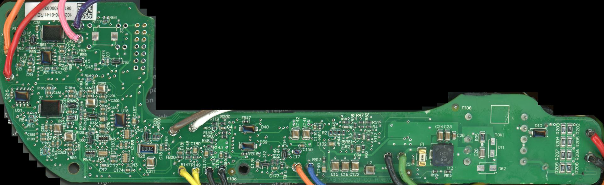
Long story short, pretty cool. It definitely seems like an overkill design for what should have just been a pretty simple device. Instead Tesla has a 32-bit processor on here, a few temperature probes, HV sensing, and a bunch of other stuff that probably could have just been handled by in-car firmware and a relatively dumb adapter. Probably wouldn't have been my design, but hey, whatever works.
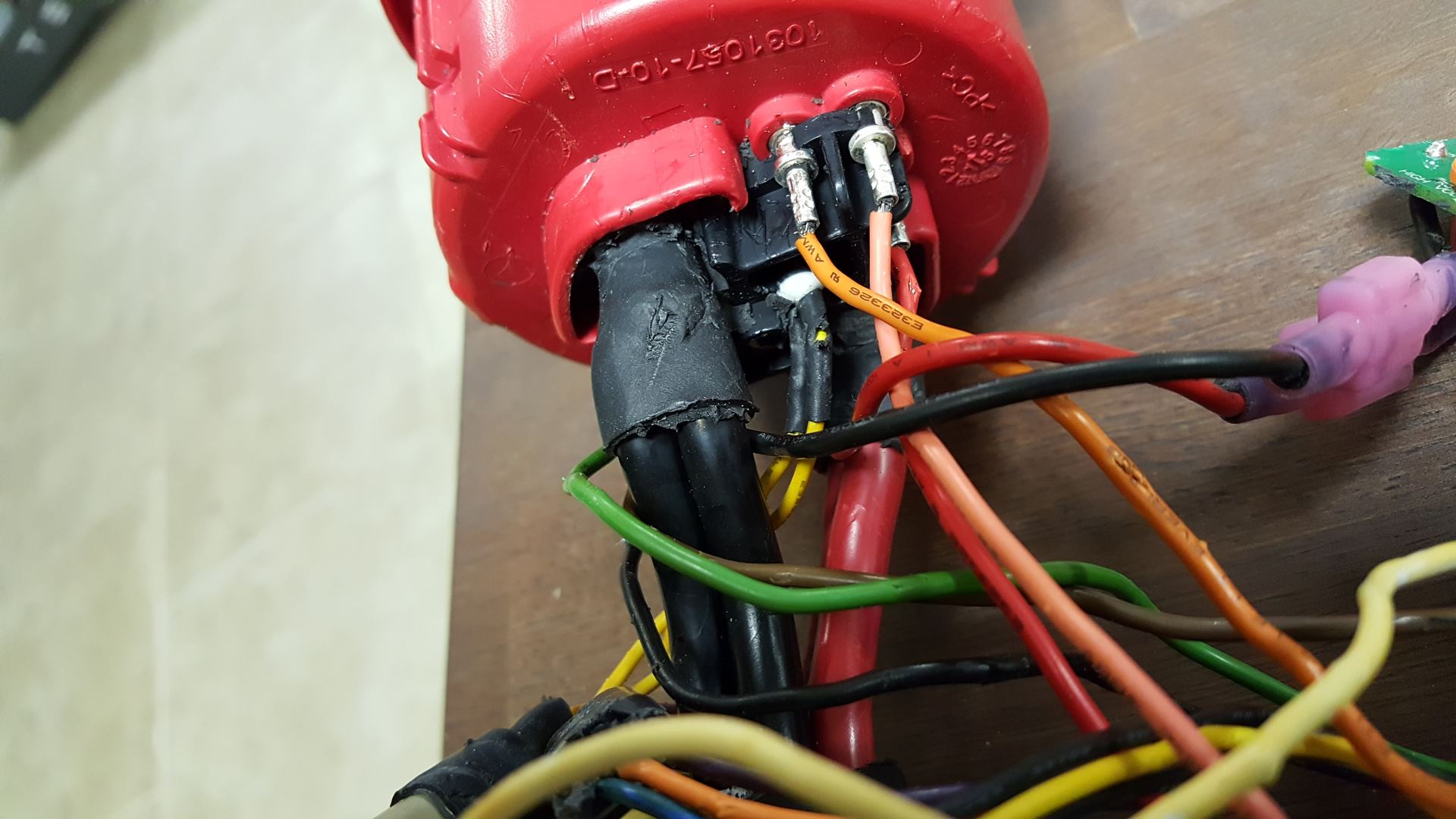
The charge connector appears to use parallel #6 gauge (guestimate) conductors for each terminal, and Tesla gives it a rating of 125A continuous. That's a good 40-50kW at 85 kWh pack voltages. Assuming it's actually #6 that would be 150A combined NEC rating, or about 120A continuous, which is close enough. Interesting because this is the first Tesla charging related item that actually seems to mostly conform to NEC amperage ratings for the wire. (Obviously not completely, since parallel #6 aren't allowed per NEC, but we won't get into that here).
The charge connector is physically much larger than the HPWC or UMC connector in order to handle the higher gauge wiring.
Overall it's a pretty rugged design.
---
Edit: At some point my copyrighted externally hosted images were illegally copied from my external hosting and re-hosted directly by TMC without notice or permission. TMC was NEVER given permission to host and distribute my copyrighted images. I've corrected the image references. If my images are appropriated again without my permission I will be forced to take legal action.
Probably one of the most annoying things I've ever taken apart. The housing was put together with the board and wiring and all, then injected with rubber potting material. So nearly 100% of the innards were imprisoned inside solid rubber. Awesome for the design, terrible for me.
Here is a shot after I finally removed some of the rubber that was on top of the PCB portion.
Working off and on at it over several hours picking at the rubber trying not to damage the board I finally was able to free it. I caused some damage to the low voltage wiring while trying to free everything from its rubber prison, but, not an issue since I won't be using it as it is for my upcoming project.
All of the rubber pieces I pulled out of the thing swept up... definitely a pain.
Here are some shots of the PCB front and back. Click for very high resolution versions.

Long story short, pretty cool. It definitely seems like an overkill design for what should have just been a pretty simple device. Instead Tesla has a 32-bit processor on here, a few temperature probes, HV sensing, and a bunch of other stuff that probably could have just been handled by in-car firmware and a relatively dumb adapter. Probably wouldn't have been my design, but hey, whatever works.
The charge connector appears to use parallel #6 gauge (guestimate) conductors for each terminal, and Tesla gives it a rating of 125A continuous. That's a good 40-50kW at 85 kWh pack voltages. Assuming it's actually #6 that would be 150A combined NEC rating, or about 120A continuous, which is close enough. Interesting because this is the first Tesla charging related item that actually seems to mostly conform to NEC amperage ratings for the wire. (Obviously not completely, since parallel #6 aren't allowed per NEC, but we won't get into that here).
The charge connector is physically much larger than the HPWC or UMC connector in order to handle the higher gauge wiring.
Overall it's a pretty rugged design.
---
Edit: At some point my copyrighted externally hosted images were illegally copied from my external hosting and re-hosted directly by TMC without notice or permission. TMC was NEVER given permission to host and distribute my copyrighted images. I've corrected the image references. If my images are appropriated again without my permission I will be forced to take legal action.
Last edited:
