Welcome to Tesla Motors Club
Discuss Tesla's Model S, Model 3, Model X, Model Y, Cybertruck, Roadster and More.
Register

Convert NEMA 14-50 60 amp line to Hard Wiring Wall Connector

This site may earn commission on affiliate links.
I have an EVSE that I'm looking to replace with a Tesla Wall Connector.

Here are the details:
  • 60 amp circuit previously installed, permitted, and approved with NEMA 14-50 outlet
  • Currently connected to a JuiceBox 40
  • Goal - replace Juicebox 40 with Tesla Wall Connector to get full 48 amps of output
  • I'm located in Southeast Michigan
This doesn't seem like a complicated installation- just replace the Receptacle with a whip that goes into the Tesla Wall Connector. I've contacted a few installers and had quotes ranging from $375 to $1800 for various reasons. I'm leaning towards a Tesla-certified installer as a safety precaution for insurance, but it seems like a waste considering how easy this job seems. Maybe $50 in parts and probably something that can be done in less than 30 minutes?

Given this scenario, what would you do?
 
I probably would do it myself, as long as there is enough wire available to reach the inside of the Wall Connector.

I actually replaced a hardwired Siemens EVSE with a 6-50 receptacle to use with my Tesla mobile connector. I would have gone with the 14-50 receptacle, but the installer that added the circuit didn't add a neutral wire.
Yeah, I’ve been debating just doing it myself. However, I’m concerned about homeowners insurance liability.
 
Red flag!

60 amp circuit previously installed, permitted, and approved with NEMA 14-50 outlet

The 14-50 outlet is rated at 50-amps, not 60-amps, if a 60-amp breaker is in use that is a code violation. You need to confirm the wiring is actually rated for 60-amps. Note that if it is #6 romex, for examaple, the wire is rated a 55-amps and cannot be used on a 60-amp circuit. You will also need to replace the GFCI breaker, which should have been installed, with a standard 50-, or 60-amp breaker as appropriate.

Note that the wall connector can be set to a 50-amp setting and will charge at 40-amps.

Other than checking the wire, this is definitely a doable DIY project.
 
Red flag!


The 14-50 outlet is rated at 50-amps, not 60-amps, if a 60-amp breaker is in use that is a code violation. You need to confirm the wiring is actually rated for 60-amps. Note that if it is #6 romex, for examaple, the wire is rated a 55-amps and cannot be used on a 60-amp circuit. You will also need to replace the GFCI breaker, which should have been installed, with a standard 50-, or 60-amp breaker as appropriate.

Note that the wall connector can be set to a 50-amp setting and will charge at 40-amps.

Other than checking the wire, this is definitely a doable DIY project.
interesting! The work was definitely approved for permitting as part of a larger solar install.

I was told it was a 60amp wire. The circuit breaker for it definitely reads 60 twice and the outlet is a 14-50.

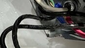
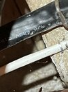
I believe I’ve identified the wire coming out of the panel connected before it goes into the wall and then conduit in my garage, but I’m having trouble reading the label info (thick black one in these photos). I’ll try to get a better look later today to see if I can verify the wire size.

264D869C-274F-4617-B085-CEE3909D577C.jpeg


635A4882-EA4A-4754-AEFE-495F82574EE5.jpeg
 
It looks doable, but I have some "not an electrician but have installed a wall charger" thoughts/observations. Assuming the wire is 4/3 NMI (Romex):
  • Make certain that it isn't aluminum wire - it's cheaper and your current box may allow it, but Tesla's doesn't
  • Splices in 4 gauge wire aren't trivial "Wago or wirenut" affairs - check out Polaris wire connectors (there might be others like that as well) and whether the splices will fit into the existing box.
  • Rather than splicing, consider mounting the wall charger higher on the wall to free up slack to make the circuit - the wall connector backwire doesn't require a junction box, just a NMI push-in connector.
  • Clip off (or wire nut) the neutral (white) wire at both ends unless you want to keep the option to replace the wall charger.
Good luck!

(Added: Amazon link to Polaris-style splice)
Polaris-style wire splice
 
Last edited:
I would not recommend this as the wire is run and you do not want to lose future options. Cap the wire at the Wall Connector and leave it connected in the breaker box.
Hence the "wire nut" part of the suggestion, but I'd still disconnect & wire nut the neutral wire in the panel so there's no question of a panel issue resulting in a hot wire at the other end.

There's not a lot of extra space inside the wall connector for an unused #4 neutral wire and wire nut. Of course, if the OP does a splice in the junction box he can terminate the neutral there.
 
I’m having trouble reading the label

I am not an electrician but the black wire (I assume this is one) "looks" like Cirtex NM-B wire. It is really hard to tell if this is 6/3 or 4/3 wire, look for such a marking. If it is 6/3 then it is limited to 55-amps, which will require a 50-amp breaker and setting the Wall Connector to a 50-amp setting. If it is 4/3 this good to 70-amps, so a 60-amp breaker and setting the Wall Connector to a 60-amp setting

 
  • Helpful
  • Like
Reactions: Rocky_H and ziptbm
My 60 amp breaker is also not a gfci breaker. There’s no test/reset on it like I have for some of the other ones.

It is possible the 14-50 was not fully wired. Normally you run 4-wires, hot-hot-neutral-ground which makes the 14-50 into a 120v and 240 outlet and requires a GFCI breaker. If the neutral wire was not run then it is a 240v only outlet and, since there is no neutral, no GFCI breaker. This would be kind of a dumb since a 6-50 outlet (240v only) is available and would be what should have been used.

I just mention this only as an FYI for when you open up the 14-50 outlet and if you don't see the neutral wire connected.
 
I need to play my usual devil's advocate role here, but are you sure you are in a position that you need 48A charging? I mean more is better, but is it necessary? Obviously your needs may actually require it, but is the extra 8A going to buy you more convenience or enable a long commute that you regularly do?

My home charging station is only capable of 30A and it is plenty capable of charging my M3LR overnight. It can replenish even a long day's worth of charge in about 90 minutes.

48A charging is great for those that have 160 mile commutes, or at places like restaurants where you want to pack in as much charging as you can while you eat dinner for an hour, but I do think for home charging, most can get by with much less.
 
  • Like
Reactions: Fiver and Genie
I need to play my usual devil's advocate role here, but are you sure you are in a position that you need 48A charging? I mean more is better, but is it necessary? Obviously your needs may actually require it, but is the extra 8A going to buy you more convenience or enable a long commute that you regularly do?

My home charging station is only capable of 30A and it is plenty capable of charging my M3LR overnight. It can replenish even a long day's worth of charge in about 90 minutes.

48A charging is great for those that have 160 mile commutes, or at places like restaurants where you want to pack in as much charging as you can while you eat dinner for an hour, but I do think for home charging, most can get by with much less.
All great points.

I really don’t like the JuiceBox and would rather have the Tesla wall cherger since it will coordinate with my powerwalls. So, since I’m upgrading, I want to be certain I get the full power to it since I already have the wiring (or so I thought…hope to confirm it’s 4 gauge soon). And my power company is basically paying for the new charger through a local incentive.

I actually have two EVSEs. My other one is 30 amp and that is fine for my needs…but it is is dumb Bosch charger, so I put a zwave switch in the line so I can measure consumption and control on/off.

Long story short, I agree with your sentiment about needs versus want.
 
I am not an electrician but the black wire (I assume this is one) "looks" like Cirtex NM-B wire. It is really hard to tell if this is 6/3 or 4/3 wire, look for such a marking. If it is 6/3 then it is limited to 55-amps, which will require a 50-amp breaker and setting the Wall Connector to a 50-amp setting. If it is 4/3 this good to 70-amps, so a 60-amp breaker and setting the Wall Connector to a 60-amp setting

Thanks for this.

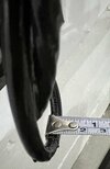
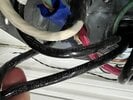
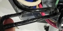
For the life of me, I can't find a good section of the wire that's legible for me to decipher if it's AWG 6 or AWG 4. I got a better-lit version of the grouped wired and pulled off one of the junction boxes to see if I could read off of the connected cable for it goes through the conduit to the NEMA 14-50, but I still can't tell what it says. Sharing a few photos in case someone here knows more about what I should be looking for or I am clearly missing.

Sounds like hiring an electrician would be best since I'm not fully confident in the line being 60 amp capable. Appreciate the input and guidance on this thread.
 

Attachments

  • IMG_6309.jpeg
    IMG_6309.jpeg
    283.4 KB · Views: 100
  • IMG_6308.jpeg
    IMG_6308.jpeg
    242 KB · Views: 85
  • IMG_6307.jpeg
    IMG_6307.jpeg
    352.2 KB · Views: 92
  • IMG_6306.jpeg
    IMG_6306.jpeg
    237.2 KB · Views: 83
  • IMG_6304.jpeg
    IMG_6304.jpeg
    289.6 KB · Views: 85
Note to all electricians reading this: Yes, this is totally and absolutely approximate and SWAG-ish. :)

I see what looks like a "THHN" in the first picture and found charts that show the *total* diameter (including insulation) for THHN #4 & #6 wires. Although there are some minor (0.00x") differences between them, they say that the diameter of #4 should be around 0.330" (8.4 mm), while #6 should be around 0.250" (6.3 mm). Although the tape end is in the way in the second picture, the wire looks closer to 6mm in diameter than 8mm...
 
Those single THHN conductors in the J box look no larger than 6awg. They are presumably from the black cable shown stapled in the wall in the earlier and final pics? If those 2 guesses are right I’d say you’re all set for 40A charging.
Yes, half of the wires are from the black cable stapled to the wall.

if is 6AWG, that means my previous installer put a 60 amp breaker on cable not capable of 60 amps…. Sounds like I need to follow up with them as it was always intended to support 48 amp charging if/when I were to upgrade from the NEMA 14-50…at least that’s how I understood it.
 
  • Like
Reactions: Rocky_H
If it is THHN 6-AWG copper wire, it is rated at 75-amps., which would make sense for a 60-amp circuit run.