Welcome to Tesla Motors Club
Discuss Tesla's Model S, Model 3, Model X, Model Y, Cybertruck, Roadster and More.
Register

Correct way of wiring OpenEVSE in Europe for 3 phase 22kW

This site may earn commission on affiliate links.
Hello all;

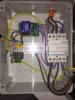
I'm about to purchase a few OpenEVSE's to install EVSEs at home, at work and build a mobile one like the Fivari charger to charge 3 phase, single phase in Europe. (whatever I have available) I believe I've looked at everything available online during research, however there's no one source to show how a 3 phase, Euro spec OpenEVSE could be done. Some people have done it but nothing is absolutely clear. In order to not lose any functionality I came up with this, what I believe would be the true way of wiring an open evse with a 3 phase power network.
3phase_open_evse_wiring.jpg

Some notes;

  • - Using the AC Relay side to power the 4 pole European contactor with 220VAC coil. I don't think there are any contactors with this much power handling, using 12V DC coils. I hope this is the correct way to wire. (some controllers have two outputs for both A1-A2 terminals on the contactor, I assume with OpenEVSE AC Relay H is to close contactor, AC Relay N is for neutral and A2 of the contactor is to energize, hence L1, I may be terribly wrong with this but it is what I came up with after seriously spending time looking at Viridian, Mainpine, SmartEVSE and OpenEVSE wiring cases)
  • - Using the OpenEVSE built in GFCI for GroundCheck success and also using an external RCD to protect for all three phases. Is there a way to connect the RCD to EVSE GFCI pins to get that check without the built in GFCI?
  • - To see energy consumption in the LCD, I am putting only a single phase through the current measuring CT, this will only show amperage per phase.
  • - AC test's both (L3-L2) goes to output of contactor so it would sense 220V AC on both test terminals (in ref. to ground of OpenEVSE board, otherwise 400VAC between both phases, I don't know how it is done) and auto sense Level 2. I hope I am correct with this logic.

Besides the wiring, for this to function properly I believe I need to do firmware modification such that;

  • - Level 2 nominal voltage for energy calculation should be 220V instead of 240. Also I need to multiply measured L3 current through CT by 3. (for 3 phases)
  • - To plug the mobile version to single phase 220V schuko, I'll connect only L3 and leave L1-L2 empty. That won't change a thing on the functionality side as EVSE doesn't tell between a single or three phase but in terms of measuring it shouldn't be multiplied by 3. So, I am thinking because this will be Level 1 charging, Level 1 energy calc. formula shouldn't be x3 measured current. It would be great if I could change the names from Level 1, Level 2 to "Single Phase", "Three Phase"
  • - I also would like to change the language of the LCD menu.
Do these make sense? Have I done my homework correctly? Could anyone direct me towards some links to edit the firmware properly? (I don't know much programming)

Thanks in advance for your help.
 
  • Like
Reactions: spottyq
  • - Using the OpenEVSE built in GFCI for GroundCheck success and also using an external RCD to protect for all three phases. Is there a way to connect the RCD to EVSE GFCI pins to get that check without the built in GFCI?
  • - To see energy consumption in the LCD, I am putting only a single phase through the current measuring CT, this will only show amperage per phase.
  • - AC test's both (L3-L2) goes to output of contactor so it would sense 220V AC on both test terminals (in ref. to ground of OpenEVSE board, otherwise 400VAC between both phases, I don't know how it is done) and auto sense Level 2. I hope I am correct with this logic.
.

I do not know the details of OpenEVSE, but from general principles:

  • If you want to use OpenEVSE's RCD (=GFCI) function, you must put all 4 wires - three phases and neutral - through the sense coil. If you only put one phase and neutral, it will look like a huge fault as soon as you connect a 3-phase load - the whole point of 3-phase is that most of the return current goes down the other phase wires rather than the neutral. The sense coil is measuring the net current through all the cores and expects it ro be zero- if not, some current has leaked out to earth, presumably due to a fault.
  • With 4 wires through the sense coil it will still work fine on single phase, as there will be no current in the two unused wires and it will behave as if they were not there.
  • There's in theory no need to have both an RCD and OpenEVSE's internal RCD function, as they are both doing the same job. However, if this is for permanent installation, the software RCD quite likely won't meet the requirements of your local regulations, so it's sensible to keep the external one. Given the hardware is already there, you might as well wire up the OpenEVSE one as belt-and-braces. If this is for a portable unit to connect to an existing commando socket, it might be more tempting to omit the separate RCD (as any regulatory requirement in respect of the fixed wiring is the responsibility of whoever put the socket in - quite often they will have provided an RCD already).
  • Doesn't OpenEVSE already measure the voltage rather than just assuming 240? In your case, measuring voltage and current on a single phase and multiplying by 3 should give a reasonable estimate of the total power (the actual voltage is likely to vary significantly from 220 or whatever the nominal is where you are, but the three phases will probably be roughly the same as each other, and for EV charging the currents will normally be very closely matched.
  • If the OpenEVSE you are using only has sense inputs to check the operation of a single phase contactor, there won't be enough for three phase. Arguably, welded contactor detection is less important for 32A than for 80A, and certainly many commercial designs of EVSE in Europe don't have it. If you are hacking the software, maybe you could re-purpose the sense inputs to detect the presence of L2 (and hence solve your problem of when to do *3 in the power calculation).
 
Doesn't OpenEVSE already measure the voltage rather than just assuming 240? In your case, measuring voltage and current on a single phase and multiplying by 3 should give a reasonable estimate of the total power (the actual voltage is likely to vary significantly from 220 or whatever the nominal is where you are, but the three phases will probably be roughly the same as each other, and for EV charging the currents will normally be very closely matched.


No, while older OpenEVSE modules may have measured the line voltage, the current OpenEVSE v4 controller does not have that capability and simply has 120V and 240V hard-coded into the firmware for L1 and L2 operation. If you are running on a commercial site in the US (208V) or some other voltage, you would need to recompile the firmware with your local voltage to make sure the amperage -> kWh conversion calculation is accurate. Also, since voltage is rarely exactly at the nominal voltage of 240V on a residential setup, the kWh isn't necessarily accurate on the OpenEVSE display.

I have three ways to monitor the electricity being consumed by my Nissan Leaf.

- TED 5000 mounted in the breaker panel monitoring the current to/from the EVSE as well as the voltage. This seems to be most accurate.

- Nissan Carwings website - This measures the power that the car consumes out of the battery. It doesn't include charging
inefficiencies and is therefore slightly lower than the reading from the TED.

- OpenEVSE display - This measures the same current that the TED sees (except for the couple watts consumed by the OpenEVSE controller and main
contactor), but since it assumes 240V and I typically see a few volts lower than that under load, it records slightly higher than reality for its kWh readings.
 
Hello emir-t

I am a fellow european openEVSE user from Switzerland

Just stumbled across your diagram on the forum here. You are right that there is not much documentation on European Version Tri-Phase open EVSE's around, so I am very interested on how you got on with your installation!

I have tried to build an openEVSE myself and based some wiring on your diagram.

It would be interesting for me to learn if your wiring actually worked in your installation. I am not sure if the power straight from the openEVSE is strong enough to activate the contactor. I read in other building instructions, that some other colleagues are putting in a 12V automotive relay in between, to activate the main contactor.

After a first test today with your diagram (without the 12V relay) says: CONNECTED, 0 KWH but it doesn't seem to close the contactor. I am attaching a picture of my own installation (the 12V relay in the center is unused). Would you mind having a short look at it and comment please?
In your diagram, it is not evident how the wiring to A2 on the connector is laid out exactly...

Thank you very much and best regards,
delage.
 

Attachments

  • IMG_0531 (2).JPG
    IMG_0531 (2).JPG
    325.2 KB · Views: 1,056
Hello emir-t

I am a fellow european openEVSE user from Switzerland

Just stumbled across your diagram on the forum here. You are right that there is not much documentation on European Version Tri-Phase open EVSE's around, so I am very interested on how you got on with your installation!

I have tried to build an openEVSE myself and based some wiring on your diagram.

It would be interesting for me to learn if your wiring actually worked in your installation. I am not sure if the power straight from the openEVSE is strong enough to activate the contactor. I read in other building instructions, that some other colleagues are putting in a 12V automotive relay in between, to activate the main contactor.

After a first test today with your diagram (without the 12V relay) says: CONNECTED, 0 KWH but it doesn't seem to close the contactor. I am attaching a picture of my own installation (the 12V relay in the center is unused). Would you mind having a short look at it and comment please?
In your diagram, it is not evident how the wiring to A2 on the connector is laid out exactly...

Thank you very much and best regards,
delage.

Hello Delage! Sorry for the late response.

I still haven't used to OpenEVSE. Kit has been lying down in the drawer for months. Now I'll get right to it and while checking out the old documentation I came across your message. I think in your setup AC relay "H" is going to A1 which is correct. But maybe AC relay "N" is supposed to go to A2. If the angle isn't deceiving me yours seems so to be going to Neutral and you bridged A2 with one of the phases? (#8?) I'm not an electrician but to the best of my knowledge A1 and A2 is connected. AC Relay H energizes A1 when conditions are met and car requests power, so that energy excites the contactor, closes it and the relay is connected through A2 going back to Neutral. What I'm not sure of is if we're supposed to take L2 to a Neutral source like regular contactors or if OpenEVSE AC Relay N provides that neutral within the PCB. So that could be wrong with my initial drawing but I'm not sure.

I would love it if you could update me. I'll do my setup and post here soon.
 
A couple of points on your diagram:
  • That "current measuring (optional)" doesn't look right. If that CT is for measuring the current consumed by the car, it needs to go round just one conductor (eg. L1), because if you put it round all three and the car is actually drawing three-phase, then the sum of the currents will be close to zero. Really to measure the power taken you need at least two CTs (to measure L1 and one of the others), since some cars draw on L1 only while others draw on all three phases, but I suspect the OpenEVSE hardware doesn't support this. On the other hand, if that CT is meant to be for an RCD/GFCI function (which I thought OpenEVSE also had?), it needs to go round all four wires including the neutral (but not the PE) so that you expect to read zero unless there's a fault.
  • Your diagram says "plug type 2" but has wires for CP and PP. If it's a tethered cable with a plug, then there's no PP (that gets looped back in the plug and there's no wire for it in the cable). If OpenEVSE supports a type2 socket as opposed to tethered, then there will be a PP input to read the cable capacity - but you'd also expect an output for the connector lock in that case.
 
  • Like
Reactions: arnis
Oh my. Of course current is measured on one phase per coil:D

According to IEC 61851:1 2010 Clause B.5
PP is used by vehicle to determine maximum cable/plug rating.
Doesn't actually state any requirements that EVSE should do anything with that.
If OpenEVSE understands resistor value (there is a pin for that) it would be better.
Though it appears it doesn't. Might change with software later. Maybe a button
on the handle (Tesla style) would later allow vehicle side lock disengagement.

Thanks anyway.
Updated painting:
3-phase_open_EVSE_arnis2.png
 
According to IEC 61851:1 2010 Clause B.5
PP is used by vehicle to determine maximum cable/plug rating.
Doesn't actually state any requirements that EVSE should do anything with that.
If OpenEVSE understands resistor value (there is a pin for that) it would be better.

If you have a detachable cable (so the EVSE has a socket on it), then the EVSE has to read the value of the resistor between PP and PE in order to know the rating of the cable that has been plugged in and reduce the power if necessary.

If you have a tethered cable, then there is nothing to connect at the EVSE end: the cable does not have a wire for PP, the pin at the car end is looped to PE with a resistor and is not connected to the EVSE. This is as you state at the bottom of the diagram "Resistor 220R between PE-PP at plug pins". A standard cable only has 6 wires - 5 heavy ones for L1/L2/L3/N/PE and one signal wire for PP.
 
I've seen both cables for sale with no noticeable price difference.
61851:1:2011 Annex B.5 mentions, that "EVSE shall interrupt the current
supply if the current capability of the cable is exceeded as defined by the value
of Rc". Rc can only be read from the plug (tethered or not).

I suspect OpenEVSE controller can be coded to whatever limit necessary, other's
might have a dial or DIP switches but the best/safest way is to read Rc value.
Also those dial/DIPs should be according to grid wiring not EVSE-plug wiring.
Tethered cable is a thing that fails (wear-tear) and can be replaced. In case of different
wire (or another plug with other parameters) used, EVSE would/should detect that.
Coding might not be available or could be forgot or done ignorantly.
Without PP wire, it is not possible to verify real Rc value of plug/cable.
 
I've seen both cables for sale with no noticeable price difference.
61851:1:2011 Annex B.5 mentions, that "EVSE shall interrupt the current
supply if the current capability of the cable is exceeded as defined by the value
of Rc". Rc can only be read from the plug (tethered or not).

No. In the loose-cable case, there are TWO resistors - one at each end of the cable. One is read by the EVSE, the other is read by the car.

In the tethered case, the EVSE already knows the capacity of the cable because the cable is part of the EVSE.

You must not connect both EVSE and car to the same resistor (with an extra core in the cable), since EVSE and car will now both be trying to pass a current through that resistor to measure the value and will get the wrong result when they both do it at the same time.

If the controller used with a tethered cable is designed such that you set the current with a resistor (rather than switches like Tesla's WC, or loading different software as several other manufacturers do), then you can simply have another resistor inside the EVSE enclosure.

A cable with an extra core would be useful if you want to build a Tesla-specific cable with a transmitter to open the chargeport - Tesla use such a cable to supply power to the transmitter, mounted inside the connector.
 
In the loose-cable case, there are TWO resistors - one at each end of the cable. One is read by the EVSE, the other is read by the car.
True, IEC drawing actually shows exactly that, Mode3 Case B.

You must not connect both EVSE and car to the same resistor (with an extra core in the cable), since EVSE and car will now both be trying to pass a current through that resistor to measure the value and will get the wrong result when they both do it at the same time.
Why are L1+L2+L3+N+PE+PP+CP cables readily available on the market if there may not be PP connection according to IEC standard?

6mm2%203P%20end-on.png
 
Why are L1+L2+L3+N+PE+PP+CP cables readily available on the market if there may not be PP connection according to IEC standard?

Because Tesla use them for their cables (extra wire is power for the chargeport opening transmitter)?

Because there is some application other than EV charging for these cables?

Because someone made a mistake (like the fact that USB-standard-A-male to USB-standard-A-male cables used to be widely available despite having no useful purpose)?
 
They are being sold as EVSE cables. Maybe some EVSEs have controller
and Type2 socket not in the same casing. OK, let it be:D

Will OpenEVSE operate with nothing on PP pin? (or should I ask, does the firmware allow that)?

If it's fine, then this one should be final:confused:
Though, in case of
a) voltages between phases are way off
b) controller is unable to display/report correct total power (3x multiplication)
c) vehicle actually draws on one phase
there might be a problem with correct total power display/reporting(WiFi).


3-phase_open_EVSE_arnis2.png
 
Last edited:
To the best of my knowledge if no resistance is sensed between PP and PE car will charge from the bare minimum of 6A. 680Ohms is 16A and 220Ohms is 32A signaling for cable's capacity. After all AC charging power is determined by the weakest link of these 3;

- AC source supply capacity
- Cable capacity
- Vehicle charger capacity.

I too am confused on the point of EVSE cable being 5g6mm + 2 0,5mm universally. You never need the PP cable. PP is almost always a loop between PP-PE, it never extends from car to EVSE or vice versa.
 
At another forum somebody hinted that with button there is another resistance value.
I read more of that 61851 standard and there it was: Mode 3 case C.
Without button and tethered cable, there should be 150 Ohm resistor between PE and PP.
Only vehicle side plug. Nothing on the other side. That should apply to Type 1 AND Type 2 tethered.
With button, 330 Ohms resistor should be added across button terminals (button normally closed).
In case of tethered cable, this should initiate STOP command. But what about plug release?
Absolutely no information about unplugging tethered Type2 plug when vehicle locked.
Will it work, I do not know. Maybe it only works with unlocked vehicle.

This only applies to tethered cable setup. And that makes sense (cable can be unplugged but not stolen).

In case of 150 Ohm resistor, maximum value is sent to vehicle on Control Pilot according to controller setup.

Notice that 150 and 480 Ohms fit well between other cable ampacity limiting values (same pins). +/- 10% allowed.

If that actually works with button, in case of OpenEVSE, that would be THE BEST option (usually private charging).

Can anybody measure Tesla EU HPWC resistance values between PE and PP pin button pressed and not.
 
I don't have an HPWC to measure, but I can tell you that if you put a switch that makes the PP open-circuit when pressed, then a Model S will unlock the port. Fitting 330R across the switch would probably be better.
 
480 Ohms should do that, not open-circuit (open circuit means 6A) (there is additional 330 Ohms around button that has been pressed)
Though an error might do the same, this is not what standard requires.

That would be awesome if any vehicle with Type2 socket will unlock.
 
Yes, I'm aware of the 330R from J1772 - however it happens to work without it. I suspect Tesla are looking for any increase in the value to signal unlock.

I think this is really a J1772 feature rather than type2 (and Tesla implement it because of their N.American origins), but it might possibly work on other type2 cars.