Welcome to Tesla Motors Club
Discuss Tesla's Model S, Model 3, Model X, Model Y, Cybertruck, Roadster and More.
Register

Custom USB splitter solution for M3

This site may earn commission on affiliate links.
Not sure you can guarantee it won't brownout the other port if you short the supply. The Tesla ports have their own overcurrent too, so all you need is to get past the limit of the Tesla port and it'll trip as well.

Also, pretty much all devices support DCP at this point. Samsung 2A isn't used almost anywhere besides on old stuff, and Apple devices respect DCP. Kind of a waste of a TPS2511-Q1, isn't it? ;)

Current limit accuracy is also another issue... with +/-10% accuracy, there's no guarantee you're going to get something that works across all ranges without accidentally hitting the Tesla built-in limit. My concern is that flash drives are definitely not all under 100mA, so if you set the current limit too high on your 2511 you don't have any method to dial that down if you have a current-hungry flash drive.

Like I said before it depends what you want/need. I designed this satisfy my needs. For someone else it may be non sense,
Its a on going project and will need some testing and feedback from end user. That is one of the reasons I shared it here to get some feedback.
 
I`m in a process of making small batch (15 boards ) for initial run. The first copy's should show up next week. Planing to 3D print enclosure for now. If there is enough interest I will order tooling (mold) for custom enclosure and use ABS material.
I am not sure
Hi all,

After using the USB Y-cable splitter for a while I wasn’t happy with 500mA charging current limitation and started to look for the USB splitter/hub that can output more than 500mA. Surprisingly, I didn’t find anything on the market.

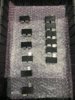
A few weeks back I started designing one (I'm a hardware engineer) and thought I'd share my solution:

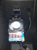
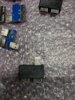
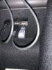
Tiny device plugs to M3 front USB port and splits the power and data in to two USB connectors (charger port and data port).

Charger port has a charging port controller chip. It will recognize the connected device and output maximum charging current (limited to 2.1A by the design).

The data lines connected straight to the second USB connector for Flash drives only (Sentry Mode/Music). It has at least 100mA current left on it, which is more than enough to run the flash drive.

Would like to get your feedback on this.

View attachment 426051 View attachment 426052
But, isn't it still limited by current supplied by Tesla Built-in USB Hub? I thought it is the one limiting total current. If you are feeding from that port, you are still limited by how much current it can provide.

In your picture/PCB, I do not see if you are feeding power from external source. Is there a external power port like some of the USB hubs have?
 
I am not sure

But, isn't it still limited by current supplied by Tesla Built-in USB Hub? I thought it is the one limiting total current. If you are feeding from that port, you are still limited by how much current it can provide.

In your picture/PCB, I do not see if you are feeding power from external source. Is there a external power port like some of the USB hubs have?

Thanks for your input!

That is correct. The limit is what M3 front USB can put out. Based on my testing it is capable to output 2.2A easily per port for extended period of time. My board will stay within that limits.

The pictures are just 3D renderings from PCB design CAD program. I have done some testing with eval boards but not with actual boards.
The boards are currently in the production and will be ready next week or two.

Thanks for quick response.

Right, with few firmware version ago they increased max current to 2.0AMPs. So, this hub design give one port with 100mA current for USB drives.
2nd port act as a strictly charge port
or does the 2nd port act as regular USB port with 2 AMP output?
 
Thanks for quick response.

Right, with few firmware version ago they increased max current to 2.0AMPs. So, this hub design give one port with 100mA current for USB drives.
2nd port act as a strictly charge port
or does the 2nd port act as regular USB port with 2 AMP output?

This hub dedicates one port for charging propose only with charging controller circuit.
The second port is straight connected (bypassed) to the car USB port.
Amusing car total current output is 2.2A. The charger will take 2.1A and 100mA will be left for second port (Flash drive or SD card).
The idea is do not exceed the maximum current output on the car USB port.

Any chance there’s power budget to allocate 200mA to the flash drive port? I ask because right now I’m using a Raspberry Pi Zero W as a flash drive so it auto-uploads images to my NAS when on WiFi.

I can go back to a standard flash drive but it’s be pretty sweet to have my cake and eat it too. :)
 
Any chance there’s power budget to allocate 200mA to the flash drive port? I ask because right now I’m using a Raspberry Pi Zero W as a flash drive so it auto-uploads images to my NAS when on WiFi.

I can go back to a standard flash drive but it’s be pretty sweet to have my cake and eat it too. :)

Actually, its more than 100mA. I was able to successfully pull 2.5A from single port for a good amount of time without noticing any voltage drop or excessive heat (max limit: cuts off right after 2.6A)
As you can see in the pictures below at 2.5A load the voltage drop is only 9mV (most likely the USB connector contacts) compare to 2.2A load. I can charge the iPhone with 2.1A and pull 300mA from data port without problem
In this design I don`t have any current limitation on data port but can easily add something that will cap it around 300mA.

Image_2_2A.jpg View attachment 426260 Image_2_6A.jpg
 

Attachments

  • Image_2_5A.jpg
    Image_2_5A.jpg
    707.5 KB · Views: 198
  • Love
Reactions: dmurphy
The front ports putting out 2.5a steady has been well known for a while, not sure why people keep thinking it's much lower or only recently bumped or something...


that's from over a year ago showing 2.5a steady and solid, shutdown at 2.6
 
  • Like
Reactions: Navak
Actually, its more than 100mA. I was able to successfully pull 2.5A from single port for a good amount of time without noticing any voltage drop or excessive heat (max limit: cuts off right after 2.6A)
As you can see in the pictures below at 2.5A load the voltage drop is only 9mV (most likely the USB connector contacts) compare to 2.2A load. I can charge the iPhone with 2.1A and pull 300mA from data port without problem
In this design I don`t have any current limitation on data port but can easily add something that will cap it around 300mA.

View attachment 426259 View attachment 426260 View attachment 426261

Feeding the Nomad wireless charger so it can output a full 7.5W Qi wireless on both sides, and run the RaspPi? That's the dream. :)
 
Hi I've just got your splitter and it seems to be working! The only suggestion I have is to label the ports, otherwise good job.
Hi,

Im glad you like it and thanks for the feedback. The current enclosures are 3D printed. Im working on a official enclosure that will have proper markings and single screw in the middle to secure top and bottom parts. Once its ready will send you the replacement unit. Please let me know if you have any questions.