Welcome to Tesla Motors Club
Discuss Tesla's Model S, Model 3, Model X, Model Y, Cybertruck, Roadster and More.
Register

Delta M-4, String drops out to zero for 2 hrs ? [delta inverter issues]

This site may earn commission on affiliate links.
ok. so you have a system designed by Tesla/Solar City where 3 PV strings output greater than 12A per string persistently for up to 4hrs recently (to be precise 12.5A), and an 8kW inverter that accepts no more than 12A per input string and persitently faults and resets in an oscillatory fashion when >12A (as designed for safety purposes), and very little power gets produced. Hmmm ... please enlighten me further thanks.

This does not necessarily mean that he is correct (its waay above my knowledge level) but @nwdiver works in the PV industry.
 
No... but I understand how PV systems operate. The current output of a solar panel is based on insolation of 1000w/m^2 but that number can easily be exceeded by something called 'cloud edge effect' so if the inverter allowed the PV array to push current it would trip on a partly cloudy day everytime there's a break in the clouds. Inverters are designed with this in mind. The critical threshold isn't the max DC input the inverter can use (12A) .... but the max DC input it can handle under a fault condition. Which is 15A in your case. But that's only if there's a fault. You could have 4MW of panels connected to the inverter and it's only going to take 12A. The 15A is just to make sure the inverter doesn't vanish in a puff of blue smoke if there's a short...

Bottom line is the only way too many panels can CAUSE a problem is if they exceed 600v. A good analogy would be a dam. You can't damage a dam by increasing the area or volume of the reservoir. Only by increasing the height. The height of the reservoir is analogous to the voltage of the PV systemyou a
 
No... but I understand how PV systems operate. The current output of a solar panel is based on insolation of 1000w/m^2 but that number can easily be exceeded by something called 'cloud edge effect' so if the inverter allowed the PV array to push current it would trip on a partly cloudy day everytime there's a break in the clouds. Inverters are designed with this in mind. The critical threshold isn't the max DC input the inverter can use (12A) .... but the max DC input it can handle under a fault condition. Which is 15A in your case. But that's only if there's a fault. You could have 4MW of panels connected to the inverter and it's only going to take 12A. The 15A is just to make sure the inverter doesn't vanish in a puff of blue smoke if there's a short...

Bottom line is the only way too many panels can CAUSE a problem is if they exceed 600v. A good analogy would be a dam. You can't damage a dam by increasing the area or volume of the reservoir. Only by increasing the height. The height of the reservoir is analogous to the voltage of the PV system.

View attachment 655492

Fair enough.

Please allow me to re-cast my orginal question as perhaps the Delta M8 inverter is mismatched or miscongiured (vs undersized) to the array of solar roof tiles as presently configured into 3 mppt input strings, that in turn frequently exceed the 12A per string limit and put the system into oscillation with low net power output? Note no individual mppt string has exceeded 480V to date.

So i see my options as:

1) find a different inverter in the 8kW range with capacity for >3ea mppt inputs so that the individual string currents wont exceed 12A. I'm guessing that may require pulling up tiles and reconfiguring strings.

2) continue to modify the Delta M8 firmware to more gracefully handle the current peaks. Tesla/Delta pushed at least one firmware upgrade since feb2021 pto in this regard. my guess is only modest improvements can be accomplished this way.

3) disable tiles in each string.

Any other suggestions?

1) The only other commercially available inverter I'm aware of that has 3 MPPT inputs is SMA but their channels are limited to 10A. I'm 100% certain this won't cause the inverter to trip as long as something else isn't wrong but it would probably cause a bit of clipping especially on hot days. Plus Tesla might use this as an excuse to void your warranty...

2) This is probably your least bad option. Keep bugging Tesla. Maybe they'll replace the Delta with a Tesla inverter.

3) Tiles add voltage. Strings add current. IIRC the Tesla roof tiles are 5-6A max power current. So I think you have 2 strings paralleled for each channel. Disconnecting one of these strings would cut the current to that channel in half.
 
Tesla emailed back today after 2 weeks.. They updated the firmware last week and basically said the variability in output is due to weather...?


" Prior to the update the performance was good, with underperformance possibly being attributed to regional weather. Seasonality affects a solar system much more and it produces a little less in the winter equinox than in summer equinox. This is considered vastly in the modeled annual output of the system."


Not sure how that explains a string drop for two hours on sunny, blue sky day....oh yeah, it does not.


Its been poor weather the last week or so, so will wait for some sunny days to see if the problem returns.


...In the mean time, anyone seen this Reddit thread on jumpers missing in the inverters causing a similar problem?


Can anytime send some snaps of their inverter jumpers so we can compare?
 
  • Informative
Reactions: jhn_
No picture of the jumpers but from what I've gathered is that the jumpers are used to split a single string between the two MPPTs.

If you login with the app you'll be able to see that both PV1 and PV2 should have the same values when the solar is producing. Without the jumpers only PV1 would have values and it would get maxed out.

There's anther known issue with these inverters when used with MCIs that can cause the inverter to shutdown for 20 minutes at a time. They claim to have a firmware fix coming for it but it's been a year+ in the works.
 
It’s very rare for a jumper to be required. 99% of the time this is laziness or ignorance. If you have two strings and a jumper... demand that they run a separate line for the 2nd string. Seriously.
Yeah, if I had known more about this all during the install I would have had them run two seperate strings. It would help my production a ton I think because of some evening shading on one of the groups of panels.
 
  • Like
Reactions: nwdiver
No picture of the jumpers but from what I've gathered is that the jumpers are used to split a single string between the two MPPTs.
There is more than one kind of jumper. Here's an image of my M8-TL-US as most recently set up by Tesla. The lower jumpers are black wire with I assume a resistor (probably greater than 1Mohm) that are connected between PV3+ and PV3- and PV1+ and PV1-. The upper jumpers are a flat red connector between PV2+ and PV3+ and a flat white one between PV2- and PV3-. These can carry current. I have since removed the current carrying jumpers since I believe that they confuse the MPPT and also are less effective in gathering low insolation. Early results suggest a 5% increase under good sun.

Also, a neighbor has a 4kW system with the M4-TL-US and it was clipping at 2.8kW. Simply upgrading the firmware from 2.2.11 to 3.1.7 brought their power up to 3.4 on a less than sunny day. I haven't asked how much they are getting when its completely sunny.
20210424_122522.jpg
 
  • Like
Reactions: lucassaugen
There is more than one kind of jumper. Here's an image of my M8-TL-US as most recently set up by Tesla. The lower jumpers are black wire with I assume a resistor (probably greater than 1Mohm) that are connected between PV3+ and PV3- and PV1+ and PV1-. The upper jumpers are a flat red connector between PV2+ and PV3+ and a flat white one between PV2- and PV3-. These can carry current. I have since removed the current carrying jumpers since I believe that they confuse the MPPT and also are less effective in gathering low insolation. Early results suggest a 5% increase under good sun.

Wow... so they ran separate lines AND jumpers to connect the strings?!
 
Wow... so they ran separate lines AND jumpers to connect the strings?!
It's a longer story. First they Y jumpered the south and west strings on the roof, brought down one set of wires, and ran them into one MPPT channel. So clipping at 12 Amps. Next, they ran separate wires, connected to PV1 and PV2, but jumpered these together at the inverter. So no clipping but obviously still wrong given that the strings are not facing the same direction. Most recently they removed the jumpers between PV1 and PV2, but surprisingly moved the jumpers to between PV2 and PV3, so that the south facing string was feeding 2 MPPT channels at ~5A each. That's the picture I showed above. I didn't bother to ask them back a 4th time-I just removed the jumper between PV2 and PV3, so that PV2 is now seeing ~10A, and the M Tool app shows PV3 as not connected. It's too soon to tell if this will make a difference.

PTO was December 18, and their last change was on April 12. The plans and permits were for a SolarEdge inverter, and the diagram for that has two completely separate arrays. I suppose that the change to Delta happened just before the installation. The tech who came and established that they had installed Y jumpers on the roof told me that the wiring diagram (which I don't have--I have only the SolarEdge version) showed it that way, but he was surprised that they actually wired it per the drawing. I have no idea why they subsequently brought down separate wires from the two strings but still connected them in parallel at the inverter. I really get the sense that Tesla has problems at the engineering level, complicated by service techs and installers who are pretty much obliged to go by what engineering tells them.
 
  • Informative
Reactions: nwdiver
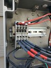
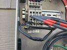
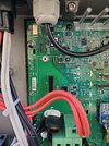
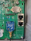
Here is what my M4 looks like.
I was not sure if that jumper post was talking about wire jumpers or circuit board jumpers...
 

Attachments

  • 20210425_101912.jpg
    20210425_101912.jpg
    406.5 KB · Views: 64
  • 20210425_101924.jpg
    20210425_101924.jpg
    296 KB · Views: 54
  • 20210425_101949.jpg
    20210425_101949.jpg
    545.4 KB · Views: 45
  • 20210425_101958.jpg
    20210425_101958.jpg
    555.5 KB · Views: 42
Another follow-up...

After a full day of sunshine yesterday, it appears things are working properly, so maybe those "firmware updates" fixed things? Here's what the day's voltages, currents, and power look like:

1619809771090.png


This added up to 33.55 kWh of production yesterday, which appears to be in line with my estimates from PVWatts for my 5.44kW system at this time of year:

1619809824287.png
 
Yesterday and today were fine for me. No drops.
I am not flat topping like the best day earlier this month...I spent less time at 3.9-4 kw than before.

Makes we wonder if the firmware update is clipping the input harder ? 5% if, so.

Here is today's output (full sun)
 

Attachments

  • Screenshot_20210430-135414_Tesla.jpg
    Screenshot_20210430-135414_Tesla.jpg
    71.8 KB · Views: 51