


This is a good solution for those who can't mount their Valentine One radar detector behind the windshield because the metal film in the windshield blocks the radar signals.
Thanks to @CHG-ON for the idea. When I read about that setup, it was obvious that it was the best solution for this situation. I decided to document my installation so there are step-by-step instructions for others who want to give it a try.
Before starting, be aware that there are some disadvantages to locating it this way, so read on to see the pros and cons.
Pros:
Cons:
Checking the windshield metal film
Before starting, check to see if your windshield has a cutout in the metal film big enough to mount the Valentine One behind it. If so, don't do this procedure--mounting the radar detector in the traditional position near the top of the windshield is a better solution if it's available to you. Here's how to check for a cutout in the windshield film:
@whitex has a good picture of what to look for here. I found that it's much easier to see the metal film when the car is outside in daylight, rather than trying to use a flashlight in a garage or other dim location. Move your head and try to catch the edge of the reflective metal film in the light. The edge of the film is very close to the edge of the frit (the black bumps at the edge of the windshield). Once you've found the edge of the film, follow it toward the center of the windshield, looking for a cutout near the rearview mirror area. Mine clearly had no cutout.
Parts needed
This procedure requires common tools that I'm not going to try to list. Some necessary less-common tools:
This installation was on my Model S. There could be some variations depending on build date, market, and options. Mine is a USA market car, left hand drive, February 2015 build date, rear wheel drive, later nosecone style, Autopilot 1 hardware, magnesium front carrier, 12 parking assist sensors, and Homelink. I'll point out the variations that I'm aware of in the relevant steps.
Most importantly, the fuse position that I used for drawing power is valid only for rear wheel drive Model S built from start of production through approximately September 16, 2015. You can find your build date on the VIN label on the driver's door jamb. Tesla's cutover points are usually not very clean, so if your car was built in July through October 2015, make sure that you do the tests described to confirm that you're using an appropriate power source.
I assume that this procedure will work with other brands of radar detectors, but be sure to read through the steps carefully to see how your radar detector differs from the Valentine One before starting.
Abbreviations and terms used
Off-car preparation
Phone mounting
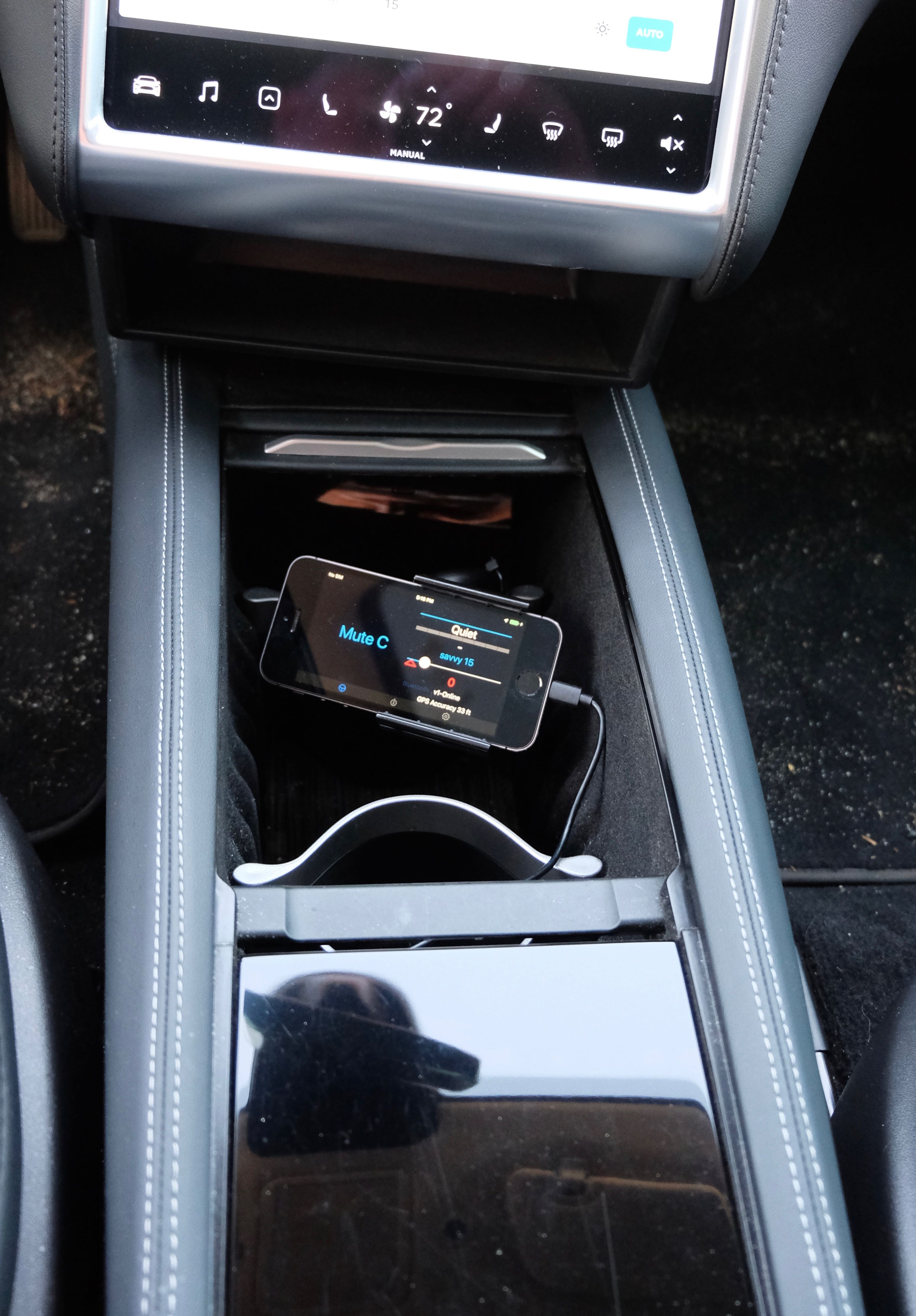
My car has Tesla's accessory drop-in center console, so I mounted the phone to one of the removable cupholder pieces deep inside and as far forward as possible. The sliding cover can be closed to hide the phone when the car is parked, and one of the cupholders is still usable, though it blocks part of the screen when viewed from the driver's seat.
Once you have a location in mind, it might be easiest to buy a cheap phone holder for a different application and repurpose and/or modify it for your setup. Look for phone holders that have a lot of adjustment potential, such as an arm with ball joints on each end. I bought one that was supposed to fit into an in-dash CD player slot and used cable ties to temporarily mount it sideways with the arm facing up. It worked fine, and the cable ties aren't very noticeable buried deep in the console, so I just left it like that.
Alternatively, you could use your own phone, if you always take it out of your pocket/purse and attach it to an instrument panel mount every time you get in the car. If you tend to keep it in your pocket/purse, it's better to use a dedicated phone because you'll want to see the screen when there are multiple signals and tap it to mute warnings.
Once you have the phone location figured out, mount the phone in its final location, or at least figure out a way to temporarily hold it in its final location. This will be needed for Bluetooth signal strength testing once the V1 is installed.
On-car preparation
Testing for the correct circuit
The Valentine One hardwire kit needs to be connected to "switched power", meaning a circuit that turns off when the car turns off. You'll notice that the HVAC and the "accessory" functions (audio, etc.) turn on when you open a door. It's not really necessary for V1 to turn on when you open the door; it only needs to be on when "starting the car" by sitting in the driver's seat and pressing the brake pedal. So, given the choice, we want to tap into a circuit connected to the "drive rails", which are the circuits that are on only when the car is in the equivalent state of an ICE car with the engine running.
I've used the Littelfuse Mini Add-A-Circuit fuse tap on other V1 installations in the past with no problems. It's a clean, easy, completely reversible way to get the power needed without disturbing the function of the circuit that you're tapping. Model S has several circuits that have 12V power connected to them and nothing else, so we can do even better than tapping into an existing circuit--we'll "tap" into a circuit that has no other purpose.
Next is determining which fuse to tap. Long story short: For rear wheel drive cars built before approximately September 16, 2015, use fuse slot F19:
If you're doing the V1 install on a Dual Motor Model S and/or a newer car, you'll need to test out several unused fuse slots using the following test. And, if you have a rear wheel drive car built before approximately September 16, 2015 and have any doubts or want to be doubly sure before you get too deep into the project, use the following test to check fuse slot F19 too.
Ideally, you'll find a fuse slot that has voltage only when the drive rails are on. Nearly as good is a fuse slot that is on the accessory rail (is on when a door is open).
Don't use a fuse slot that is on all the time, or the V1 will never shut off and "it'll drain yer battery and you'll be stranded!!!" Actually, it would take a super long time (probably years) for the V1 to drain a full HV battery, but it will be an ongoing dark current draw. Why chance things? It's easy to do a proper job.
Here's how to confirm that a circuit has switched power. The following steps are easier with a helper, but can be done without one.
Fuse tap installation
V1 preparation and test-fit
Functional test
If the V1 is not recognized, check:
V1 mounting
Securing the cables
Reassembly
Test drive
Go for a test drive. If you're already a V1 user and you're using Valentine's V1Connection app, the interface will look very familiar, but 3rd party apps will require some familiarization. Drive past some known false signals in your neighborhood to get a feel for how the app responds.
I've had my V1 installed this way for close to 2 years now, with no problems. Good luck!
Thanks to @CHG-ON for the idea. When I read about that setup, it was obvious that it was the best solution for this situation. I decided to document my installation so there are step-by-step instructions for others who want to give it a try.
Before starting, be aware that there are some disadvantages to locating it this way, so read on to see the pros and cons.
Pros:
- More functional than mounting the V1 behind the metallized windshield
- Reuse your existing Valentine One and (some) accessories
- Far cheaper than radar detectors that are designed to be permanently installed, even if you buy a new Valentine One to do this installation
- Completely hidden installation (good if you drive in states/provinces where radar detectors are illegal)
- No drilling or otherwise routing wires through the front bulkhead (no chance of water leaks)
- Totally removable/reversible except for cutting a small notch in one fuse box cover
- Use a cheap/old smartphone as an audio repeater and display screen
- Use a V1-compatible iOS or Android app to greatly increase V1's functionality using GPS-based automatic muting
Cons:
- Rear radar antenna sensitivity is poor; weak radar seemingly ahead could actually be fairly strong radar coming up from behind you
- Laser sensors are disabled
- Slightly reduced sensitivity from the detector not being mounted as high as possible (vehicles directly in front of you block the signal more, slightly less warning coming up the crest of a hill)
- Need to seal the V1 in a sous vide bag, "foodsaver bag" or other sturdy waterproof bag
- A dedicated smartphone or tablet with GPS is recommended in most cases (but it doesn't need to be new and doesn't need to have active cellular service)
- You'll need a good place to put the smartphone where it won't be attractive to thieves when parked
- Moderately challenging installation
- The alerts on my iPhone 5 are barely loud enough on full volume when it's mounted in the drop-in center console (hmm, I guess I could fix this with a small external speaker)
- You're dependent on the phone app's user interface (I use V1Driver, and it has room for improvement in this department)
- My iPhone 5 has so-so GPS reception in the center console; when the GPS accuracy is poor, auto-muting and radar logging is disabled, so it's just like a standard V1 (I'm sure this varies significantly based on phone, orientation, and location)
Checking the windshield metal film
Before starting, check to see if your windshield has a cutout in the metal film big enough to mount the Valentine One behind it. If so, don't do this procedure--mounting the radar detector in the traditional position near the top of the windshield is a better solution if it's available to you. Here's how to check for a cutout in the windshield film:
@whitex has a good picture of what to look for here. I found that it's much easier to see the metal film when the car is outside in daylight, rather than trying to use a flashlight in a garage or other dim location. Move your head and try to catch the edge of the reflective metal film in the light. The edge of the film is very close to the edge of the frit (the black bumps at the edge of the windshield). Once you've found the edge of the film, follow it toward the center of the windshield, looking for a cutout near the rearview mirror area. Mine clearly had no cutout.
Parts needed
- Valentine One with ESP (Look for the ESP logo below the volume knob) [1]
- Direct-Wire Power Adapter Kit (included with the Valentine One; available cheap from Valentine Research if you need another)
- V1connection or V1connection LE Bluetooth Module (buy this from Valentine Research)
- Littelfuse Mini Add-A-Circuit Fuse tap--I bought it from Pep Boys
- An old smartphone or tablet that has a GPS antenna and is compatible with the V1Connection app and any other enhanced app you'll want to use for added functionality (such as V1Driver); it does not need to have cell service [2]
[1] If your Valentine One isn't new enough to have ESP, you can send it to Valentine to get it upgraded at a discounted price. Enter your serial number on their website for more information. However, Valentine Ones tend to sell for good prices on eBay, so it might be a better deal to sell your old one there and buy a new one. Make sure to allow overseas bidders and shipping; Valentine only ships to the U.S. and some of Canada, so there is good demand from other countries. Buy the new one first and include all of the new and unused accessories with your old one to increase its value.
[2] Alternatively, you could use your own phone, as long as you take it out of your pocket/purse and attach it to an instrument panel mount every time you get in the car.
[2] Alternatively, you could use your own phone, as long as you take it out of your pocket/purse and attach it to an instrument panel mount every time you get in the car.
This procedure requires common tools that I'm not going to try to list. Some necessary less-common tools:
- Plastic pry tool/trim removal tool
- Multimeter (preferred) or test light
- Crimping and wire stripping tool
- Candle lighter or cigarette lighter for shrinking heat shrink tubing
- Mechanic's inspection mirror or small handheld mirror
- Locking pliers, such as Vice-Grips
- Razor scraper or utility knife
- Rotary multi-tool and cutoff wheel, such as Dremel (helpful, not required)
- Cable ties
- Crimp connector, 14-16 gauge, "stud" terminal (looks like a U shape)
- Heat shrink tubing
- Double sided foam adhesive tape, suitable for outdoor use (I used 3M "Scotch Outdoor Mounting Tape" from Home Depot)
- Sturdy waterproof tape
- Rubbing alcohol
- RTV sealant or other sealant (I used Permatex Sensor-Safe Blue RTV Silicone Gasket Maker because I already had it on-hand)
- Open-cell foam weatherstripping (optional)
This installation was on my Model S. There could be some variations depending on build date, market, and options. Mine is a USA market car, left hand drive, February 2015 build date, rear wheel drive, later nosecone style, Autopilot 1 hardware, magnesium front carrier, 12 parking assist sensors, and Homelink. I'll point out the variations that I'm aware of in the relevant steps.
Most importantly, the fuse position that I used for drawing power is valid only for rear wheel drive Model S built from start of production through approximately September 16, 2015. You can find your build date on the VIN label on the driver's door jamb. Tesla's cutover points are usually not very clean, so if your car was built in July through October 2015, make sure that you do the tests described to confirm that you're using an appropriate power source.
I assume that this procedure will work with other brands of radar detectors, but be sure to read through the steps carefully to see how your radar detector differs from the Valentine One before starting.
Abbreviations and terms used
V1 = Valentine One radar detector
V = volts
A = amps
Frunk = front trunk/underhood area
Frunk tub = the plastic cargo tub inside the frunk
NVH = noise/vibration/harshness
Bulkhead = The vertical metal panel that separates the frunk from the interior of the car, a.k.a. firewall
Bumper cover = the flexible body-color part of the bumper that you see normally
Bumper beam = the big metal bumper reinforcement hidden by the nosecone and bumper cover
Power/data cable = the phone cord that connects the V1 and bluetooth module to the power adapter
Off-car preparation
- Turn the V1 knob and lever to low volume, but not completely off.
- Seal the V1 in a sous vide cooking bag, "food saver" bag, or other sturdy waterproof bag.
- Download at least the V1Connection app (the official Valentine Research app) on the smartphone that will be used in the car. I recommend also downloading V1Driver or another V1-compatible 3rd party app for significant additional functionality.
Phone mounting
My car has Tesla's accessory drop-in center console, so I mounted the phone to one of the removable cupholder pieces deep inside and as far forward as possible. The sliding cover can be closed to hide the phone when the car is parked, and one of the cupholders is still usable, though it blocks part of the screen when viewed from the driver's seat.
Once you have a location in mind, it might be easiest to buy a cheap phone holder for a different application and repurpose and/or modify it for your setup. Look for phone holders that have a lot of adjustment potential, such as an arm with ball joints on each end. I bought one that was supposed to fit into an in-dash CD player slot and used cable ties to temporarily mount it sideways with the arm facing up. It worked fine, and the cable ties aren't very noticeable buried deep in the console, so I just left it like that.
Alternatively, you could use your own phone, if you always take it out of your pocket/purse and attach it to an instrument panel mount every time you get in the car. If you tend to keep it in your pocket/purse, it's better to use a dedicated phone because you'll want to see the screen when there are multiple signals and tap it to mute warnings.
Once you have the phone location figured out, mount the phone in its final location, or at least figure out a way to temporarily hold it in its final location. This will be needed for Bluetooth signal strength testing once the V1 is installed.
On-car preparation
1. Lower the driver's window.
2. Place the key in the car.
3. If the car has air suspension, turn on Jack Mode. You're going to be sitting in the frunk tub some of the time, and you don't want the car constantly adjusting height as you get in and out.
4. Unplug the car from the wall connector/mobile connector. You don't need to disconnect 12V power if you follow my directions, but you're going to be sitting in the frunk tub and working near live (but low voltage) circuitry, so it's better to not have the coolant pumps and fans running underneath you.
5. Remove the rear underhood apron. Pull up toward the windshield to remove.
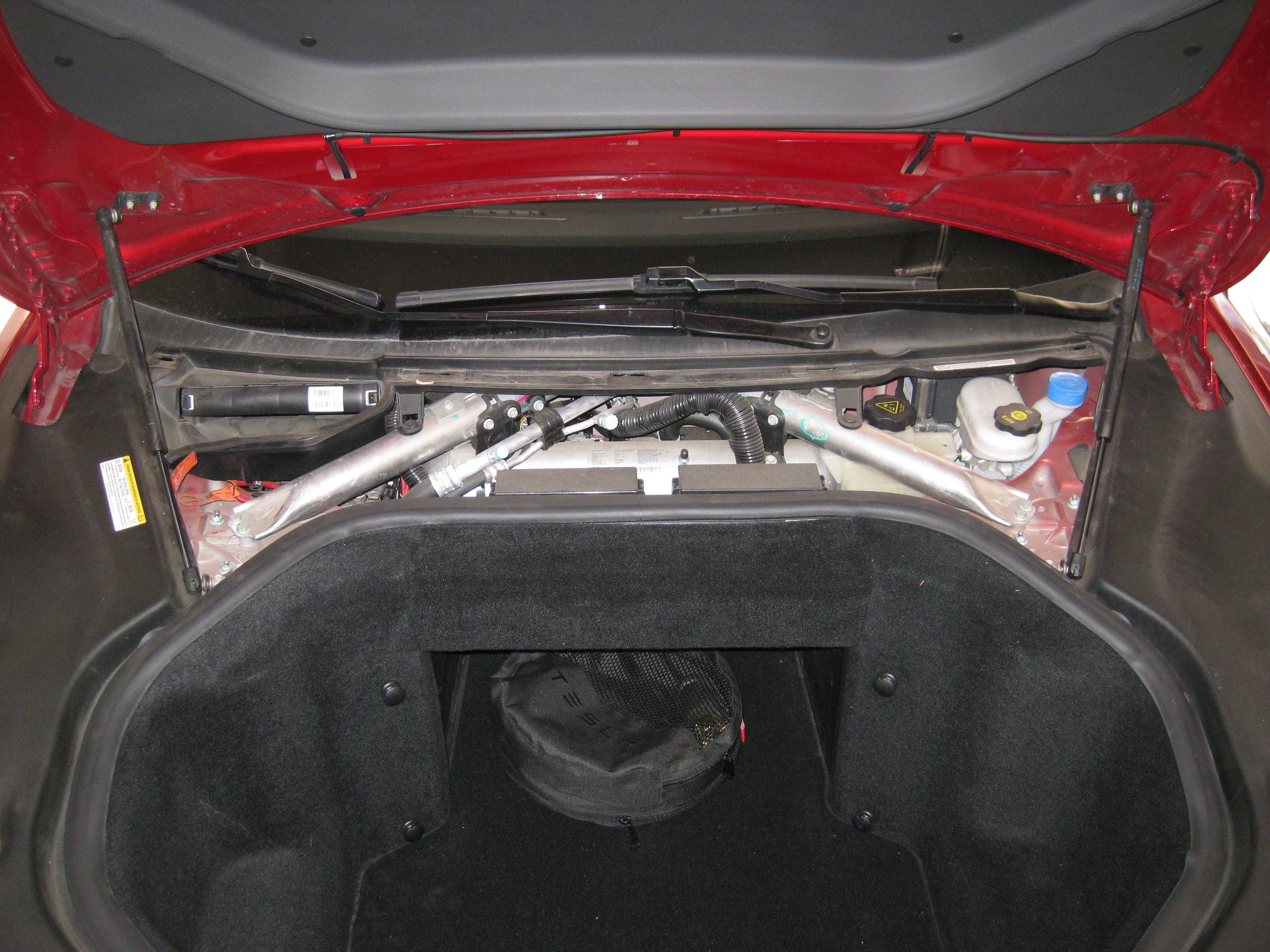
6. Remove the passenger's side underhood apron. Pull up to remove. Don't unscrew the rubber bumper, just pull up the apron to force the bumper through the hole in the underhood apron. Push the bumper through the hole as necessary.
7. Remove the HVAC filter from its housing and place it in a clean location or wrap it in a clean shop towel.
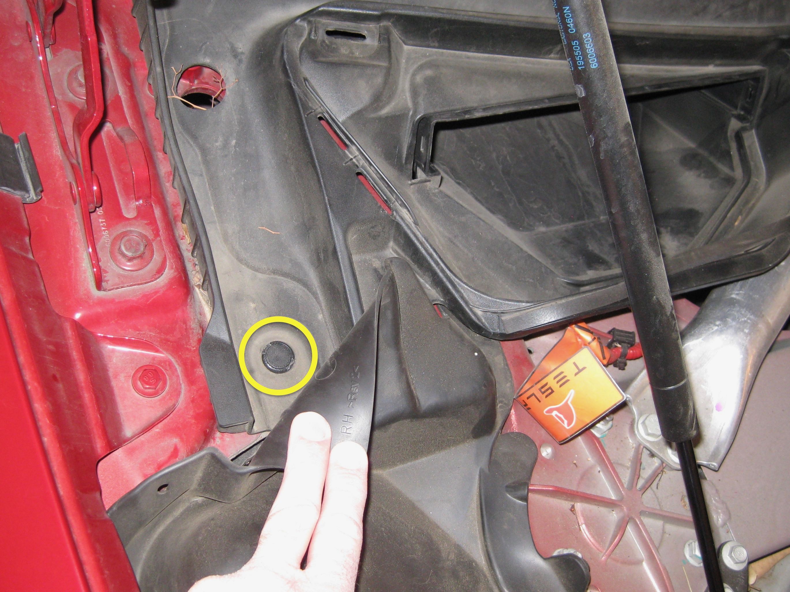
8. Remove the 3 push pin rivets that secure the cowl screen panel to the body. One rivet is hidden under the passenger's side flexible rubber shock tower cover.
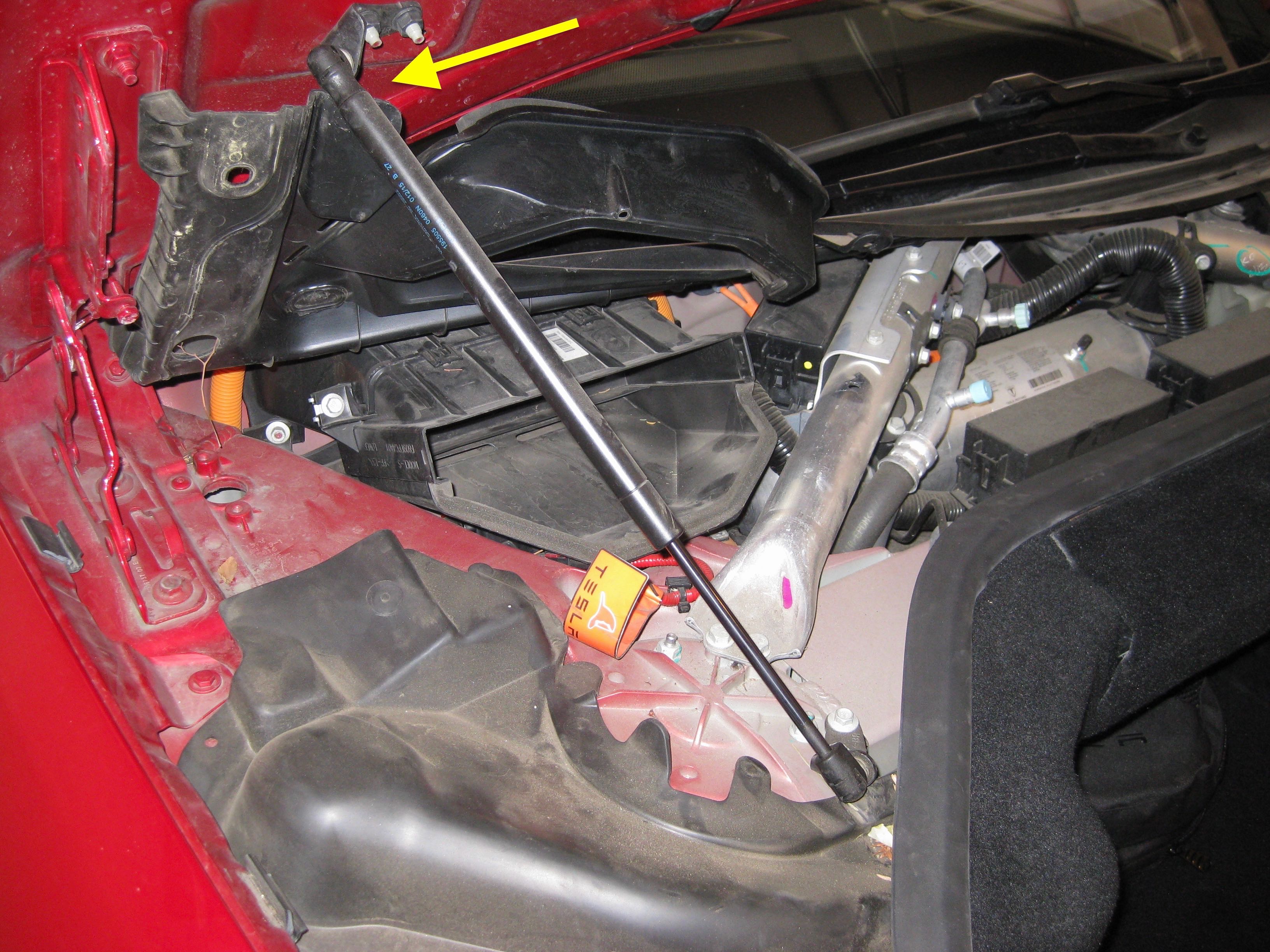
9. The cowl screen panel is flexible, so you don't need to remove it. Twist the panel and wedge the passenger's side edge of the cowl screen panel under the hood lift strut to keep it out of the way.
Optional: Remove the HVAC filter front housing for extra clearance. Remove 1 of the screws that secures the front housing. Loosen the other screw, then slide the housing off. The second screw does not need to be fully removed.
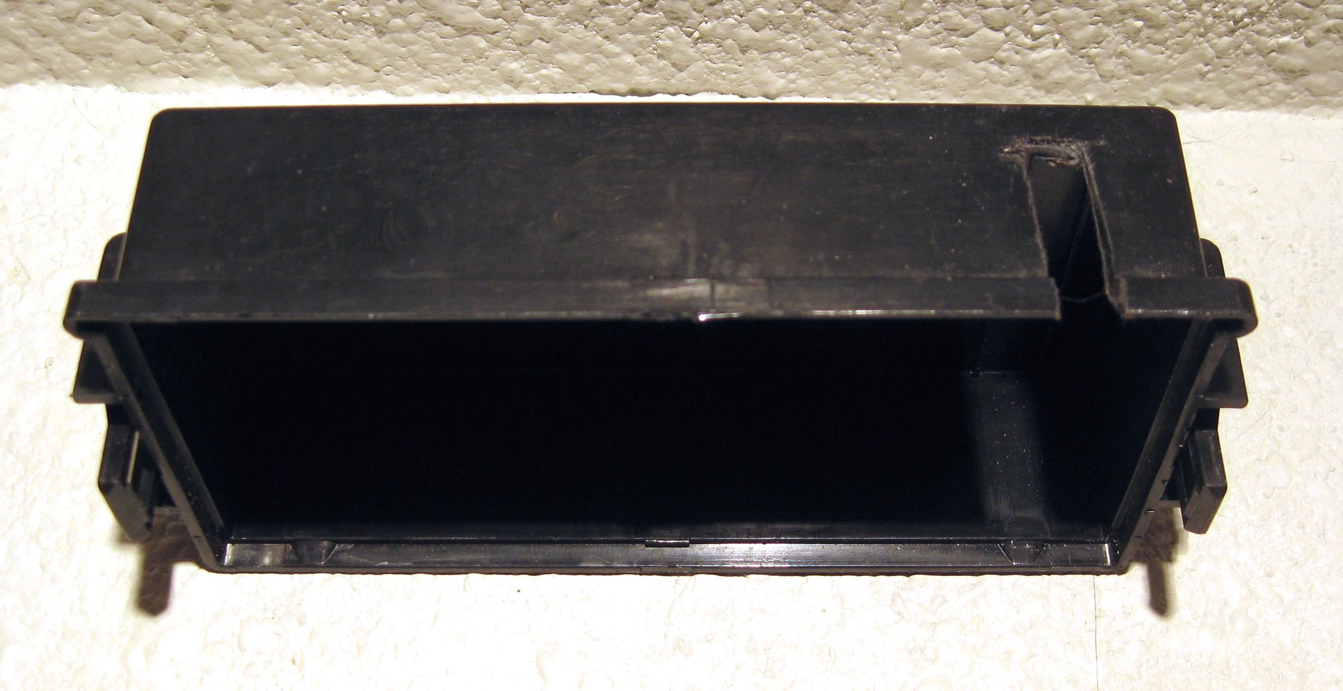
10. Remove the passenger's side fuse box cover (this is the cover on the fuse box adjacent to the HVAC filter housing).
2. Place the key in the car.
3. If the car has air suspension, turn on Jack Mode. You're going to be sitting in the frunk tub some of the time, and you don't want the car constantly adjusting height as you get in and out.
4. Unplug the car from the wall connector/mobile connector. You don't need to disconnect 12V power if you follow my directions, but you're going to be sitting in the frunk tub and working near live (but low voltage) circuitry, so it's better to not have the coolant pumps and fans running underneath you.
5. Remove the rear underhood apron. Pull up toward the windshield to remove.
6. Remove the passenger's side underhood apron. Pull up to remove. Don't unscrew the rubber bumper, just pull up the apron to force the bumper through the hole in the underhood apron. Push the bumper through the hole as necessary.
7. Remove the HVAC filter from its housing and place it in a clean location or wrap it in a clean shop towel.
8. Remove the 3 push pin rivets that secure the cowl screen panel to the body. One rivet is hidden under the passenger's side flexible rubber shock tower cover.
9. The cowl screen panel is flexible, so you don't need to remove it. Twist the panel and wedge the passenger's side edge of the cowl screen panel under the hood lift strut to keep it out of the way.
Optional: Remove the HVAC filter front housing for extra clearance. Remove 1 of the screws that secures the front housing. Loosen the other screw, then slide the housing off. The second screw does not need to be fully removed.
10. Remove the passenger's side fuse box cover (this is the cover on the fuse box adjacent to the HVAC filter housing).
Testing for the correct circuit
The Valentine One hardwire kit needs to be connected to "switched power", meaning a circuit that turns off when the car turns off. You'll notice that the HVAC and the "accessory" functions (audio, etc.) turn on when you open a door. It's not really necessary for V1 to turn on when you open the door; it only needs to be on when "starting the car" by sitting in the driver's seat and pressing the brake pedal. So, given the choice, we want to tap into a circuit connected to the "drive rails", which are the circuits that are on only when the car is in the equivalent state of an ICE car with the engine running.
I've used the Littelfuse Mini Add-A-Circuit fuse tap on other V1 installations in the past with no problems. It's a clean, easy, completely reversible way to get the power needed without disturbing the function of the circuit that you're tapping. Model S has several circuits that have 12V power connected to them and nothing else, so we can do even better than tapping into an existing circuit--we'll "tap" into a circuit that has no other purpose.
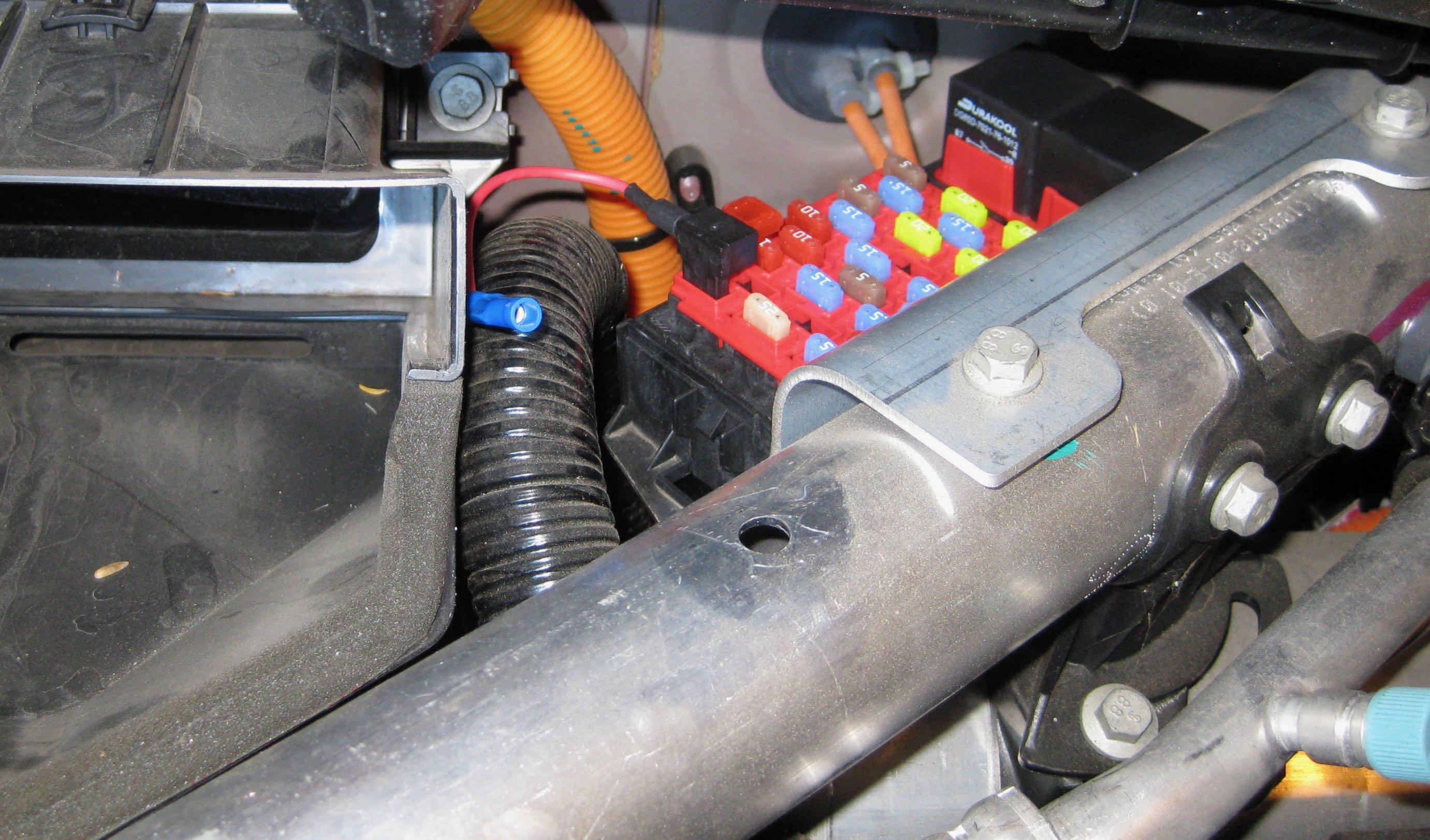
Next is determining which fuse to tap. Long story short: For rear wheel drive cars built before approximately September 16, 2015, use fuse slot F19:
If you're doing the V1 install on a Dual Motor Model S and/or a newer car, you'll need to test out several unused fuse slots using the following test. And, if you have a rear wheel drive car built before approximately September 16, 2015 and have any doubts or want to be doubly sure before you get too deep into the project, use the following test to check fuse slot F19 too.
Ideally, you'll find a fuse slot that has voltage only when the drive rails are on. Nearly as good is a fuse slot that is on the accessory rail (is on when a door is open).
Don't use a fuse slot that is on all the time, or the V1 will never shut off and "it'll drain yer battery and you'll be stranded!!!" Actually, it would take a super long time (probably years) for the V1 to drain a full HV battery, but it will be an ongoing dark current draw. Why chance things? It's easy to do a proper job.
Here's how to confirm that a circuit has switched power. The following steps are easier with a helper, but can be done without one.
- Make sure the doors are closed and the key is in the car.
- Sit in the frunk tub (don't worry, it will hold your weight).
- Look down into the desired fuse slot (use a flashlight and a mirror, if necessary). If the fuse slot is unused from the factory, there will likely be a metal terminal on only one of the 2 holes. Make a mental note of which hole that has the terminal (such as "far side", "toward the rear", etc.)
- Temporarily insert any of the fuses that are included with the fuse tap into the desired fuse slot.
- If you're using a multimeter, make sure it's set to DC voltage, not resistance.
- Touch the positive probe of the multimeter or test light to the metal tab on the top of the fuse on the side of the fuse that connects to the terminal that you noted before. Touch the negative probe to vehicle ground (exposed metal on the body). Check for voltage. There should be 0 volts. If there is voltage, this circuit is always on, and we don't want to use it.
- Have a helper open the driver's door. Check for voltage. If your circuit is on an accessory rail, there will now be ~13V. If your circuit is on a drive rail, there will still be 0V. [1][2]
- Have the helper sit in the driver's seat and press the brake pedal. Check for voltage. If your circuit is on a drive rail or accessory rail, there will now be ~13V. [1][3]
- Remove the fuse.
[1] The precise voltage isn't important for this procedure.
[2] You can do this step yourself if you don't have a helper; it's just quicker with a helper since you don't have to get in and out of the frunk.
[3] This is harder to do without a helper, but it can be done. You need to trick the car into thinking the door is closed and someone is in the driver's seat. Sit in the driver's seat with the driver's door open. Step on the brake pedal. Lean forward and fasten the seat belt behind you without lifting your hips off of the seat. Use a screwdriver, pen, or other thin cylindrical tool to rotate the door latch (on the door) 2 clicks. The first click is easy; the second click is harder and not as obvious when it's engaged. Watch the instrument cluster--the door open graphic goes away when you've rotated the door latch enough. You can now leave the car (don't close the door) and the car will stay "on" (drive rails on). It will time out and turn off after what feels like 10 minutes. When you're ready to un-do it, push the outside door handle so the car presents the door handles (remember, the car thinks the door is closed), then pull the outside door handle to "open the door" and return things to normal.
Fuse tap installation
Note: This procedure is for vehicles with the later one-piece nosecone, which were built starting in late 2012. The later (one-piece) nosecone has a smooth vertical arc below the horizontal chrome piece. The early (two-piece) nosecone has a noticeable horizontal "step" in the black plastic below the horizontal chrome piece. Early nosecones are usually replaced with the later design if they get damaged, so some 2012 cars will also have the later nosecone.
Cars with the early nosecone require the whole front bumper cover to be removed for access. This is easier than it sounds, but I'm not including the steps in this procedure. And, as you'd expect, the bumper cover would also need to be removed if you were doing this procedure on a non-nosecone Model S (built after April 10, 2016).
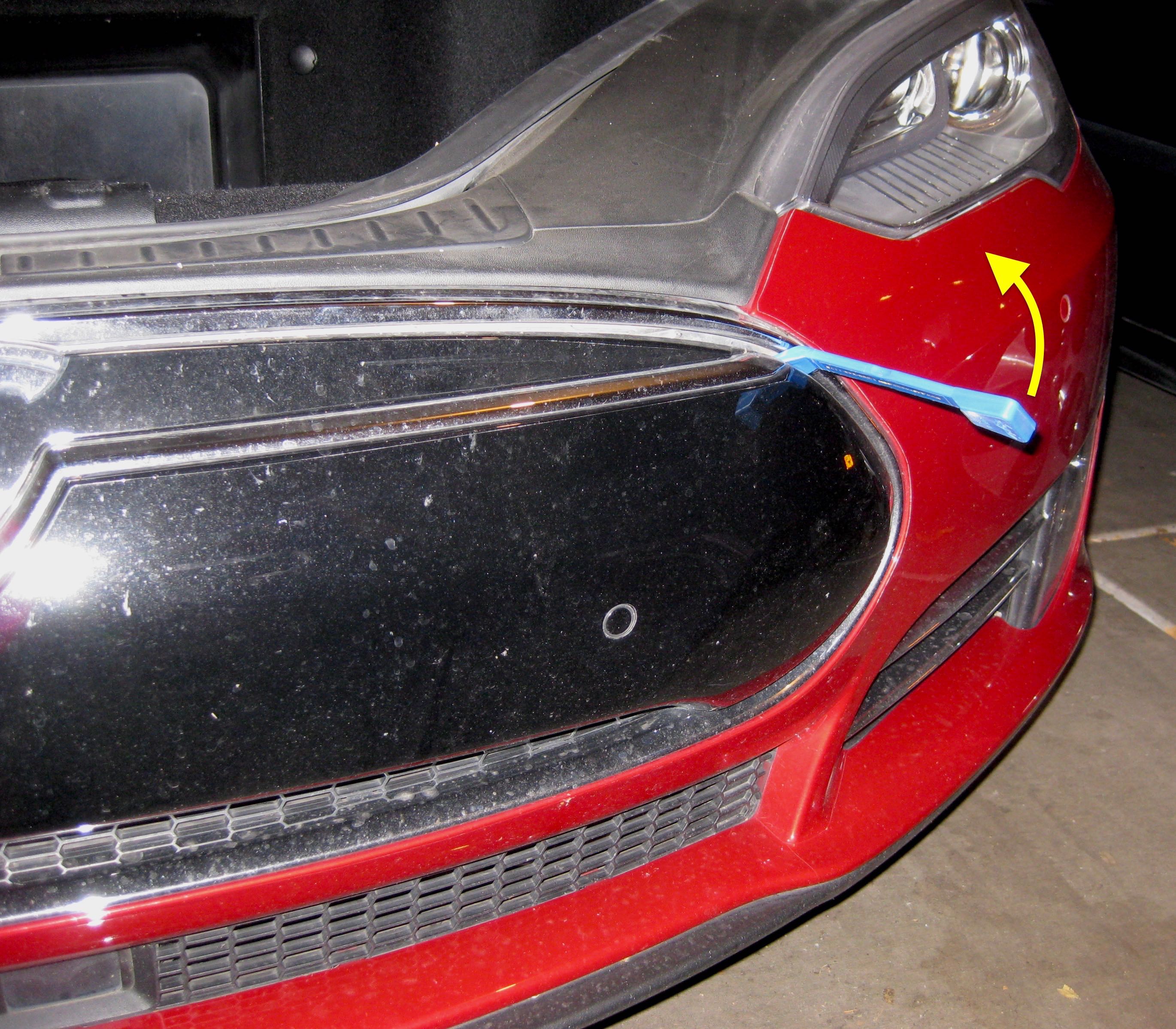
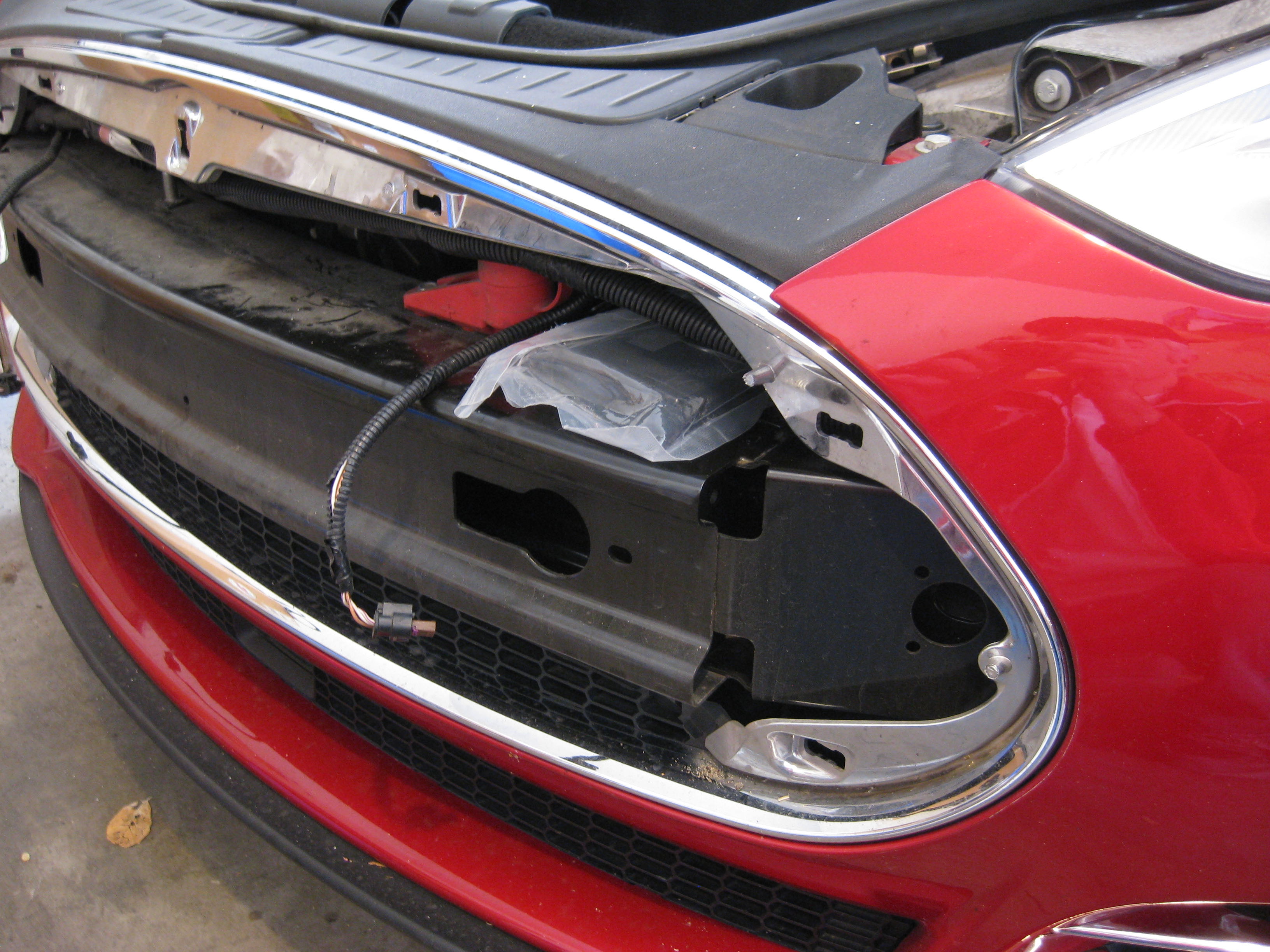
1. Insert a plastic pry tool in the upper driver's side seam between the nosecone and the chrome trim. Pry off the nosecone.
2. If the car has park assist, disconnect the sensors. It's common to let the nosecone hang from the sensor harnesses, but it's going to be in the way later, so it's best to just completely remove it now. Place it face up in a safe location. Note that when you turn the car on with the park assist sensors disconnected, an error message appears on the instrument cluster. This error message goes away when the sensors are reconnected.
3. Put the lowest-current fuse from the tap kit (that's at least 1A) in the upper slot on the tap (assuming you're "tapping" into an unused circuit). The V1 uses less than 1A.
4. Insert the tap in the direction shown if using F19. If you're using a different fuse slot, follow the instructions that came with the tap and test it in both directions.
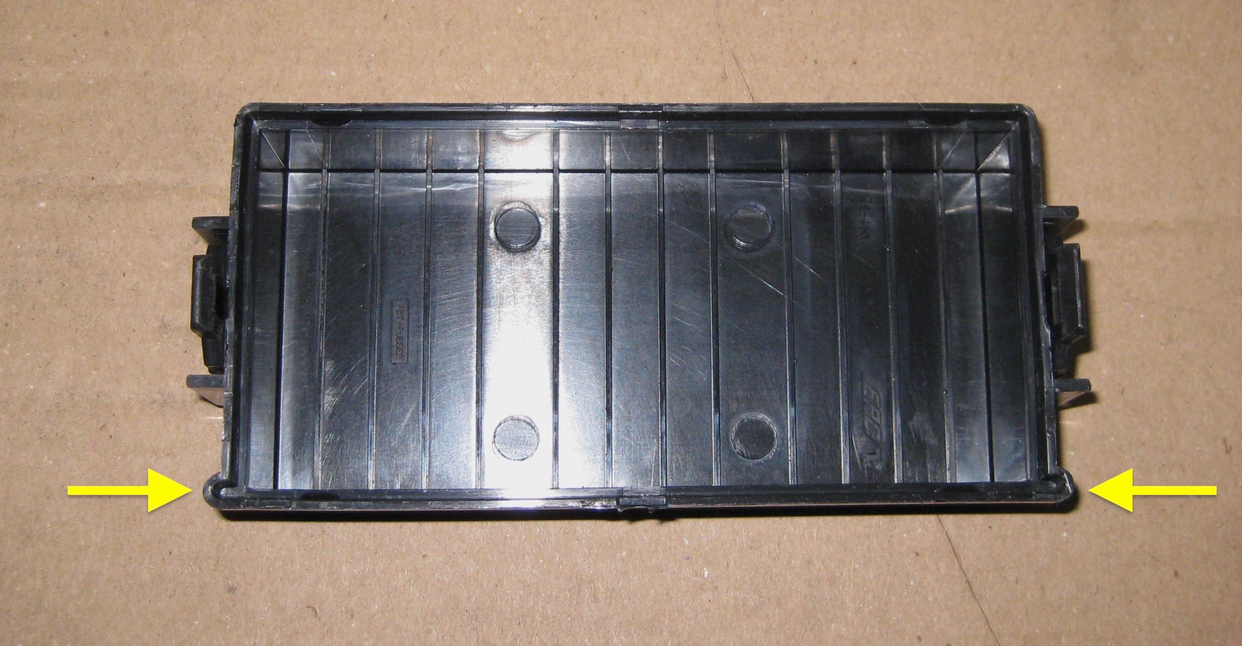
5. Position the fusebox cover over the fusebox and tap. Important: The fusebox cover is keyed to only fit one direction, which is not obvious. Make sure to position it in the correct orientation (the subtle protrusions at the bottom of the cover face toward the rear of the car).
6. Mark the location of the fuse tap wire on the fusebox cover for cutting in the next step.
7. Remove the fusebox cover.
8. It's best to start by using a drill bit to create the top of the slot, then use a rotary multi-tool with a small cutoff wheel to cut the slot below it. I had moved recently and couldn't find my drill bits, so I used the multi-tool for the whole thing, and it turned out good enough. If you don't have a multi-tool, you should be able to do it with a drill and hacksaw.
9. Test-fit the fusebox cover. Cut out additional material as needed to get the fusebox cover to close fully without pressing on the fuse tap wire.
10. Smooth out the sharp edges with rough-grit sandpaper.
Cars with the early nosecone require the whole front bumper cover to be removed for access. This is easier than it sounds, but I'm not including the steps in this procedure. And, as you'd expect, the bumper cover would also need to be removed if you were doing this procedure on a non-nosecone Model S (built after April 10, 2016).
1. Insert a plastic pry tool in the upper driver's side seam between the nosecone and the chrome trim. Pry off the nosecone.
2. If the car has park assist, disconnect the sensors. It's common to let the nosecone hang from the sensor harnesses, but it's going to be in the way later, so it's best to just completely remove it now. Place it face up in a safe location. Note that when you turn the car on with the park assist sensors disconnected, an error message appears on the instrument cluster. This error message goes away when the sensors are reconnected.
3. Put the lowest-current fuse from the tap kit (that's at least 1A) in the upper slot on the tap (assuming you're "tapping" into an unused circuit). The V1 uses less than 1A.
4. Insert the tap in the direction shown if using F19. If you're using a different fuse slot, follow the instructions that came with the tap and test it in both directions.
5. Position the fusebox cover over the fusebox and tap. Important: The fusebox cover is keyed to only fit one direction, which is not obvious. Make sure to position it in the correct orientation (the subtle protrusions at the bottom of the cover face toward the rear of the car).
6. Mark the location of the fuse tap wire on the fusebox cover for cutting in the next step.
7. Remove the fusebox cover.
8. It's best to start by using a drill bit to create the top of the slot, then use a rotary multi-tool with a small cutoff wheel to cut the slot below it. I had moved recently and couldn't find my drill bits, so I used the multi-tool for the whole thing, and it turned out good enough. If you don't have a multi-tool, you should be able to do it with a drill and hacksaw.
9. Test-fit the fusebox cover. Cut out additional material as needed to get the fusebox cover to close fully without pressing on the fuse tap wire.
10. Smooth out the sharp edges with rough-grit sandpaper.
V1 preparation and test-fit
1. Test to make sure that the bag surrounding the V1 is still air-tight. If there are any holes from handling, use packing tape or other sturdy waterproof tape to seal them. Test again for air-tightness.
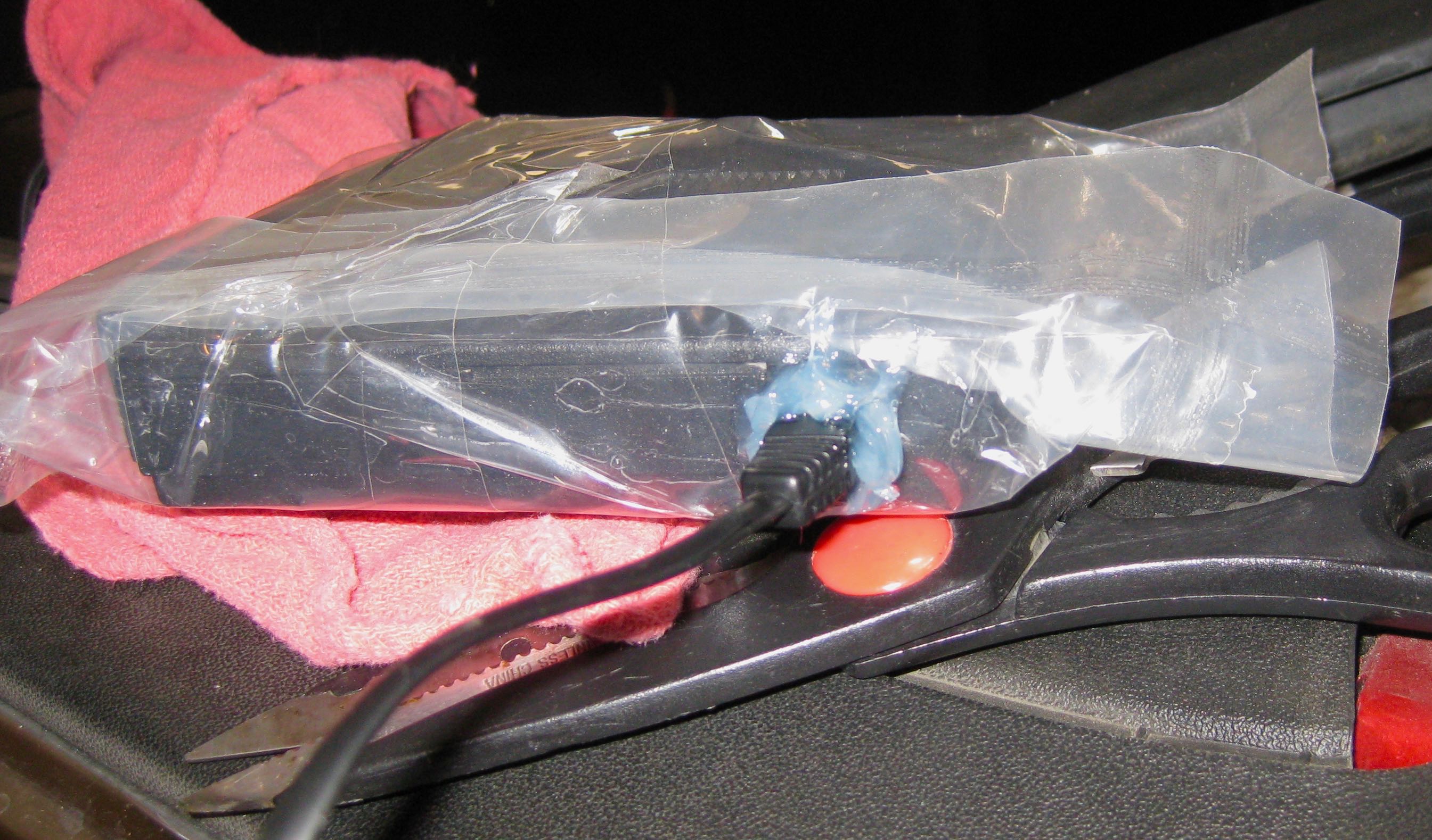
2. Poke a small hole in the bag, directly in front of the data/power inlet. Use scissors and/or a precision knife (such as X-Acto) to enlarge the hole just enough to fit the phone cord connector.
3. Retain the piece of bag material that was cut for later use, or, if there is excess material at the edge of the bag that can be cut without losing the seal function, cut off a section of the excess and retain it for use in a later step.
4. Now that the bag is no longer air-tight, fold over any excess bag toward the top of the V1 and use sturdy waterproof tape to wrap the excess bag material tight. Make sure that the bag is tight all around the V1. If this step isn't performed, the bag will be tightly sealed to the car but the V1 will slide around in the bag with each turn and stop.
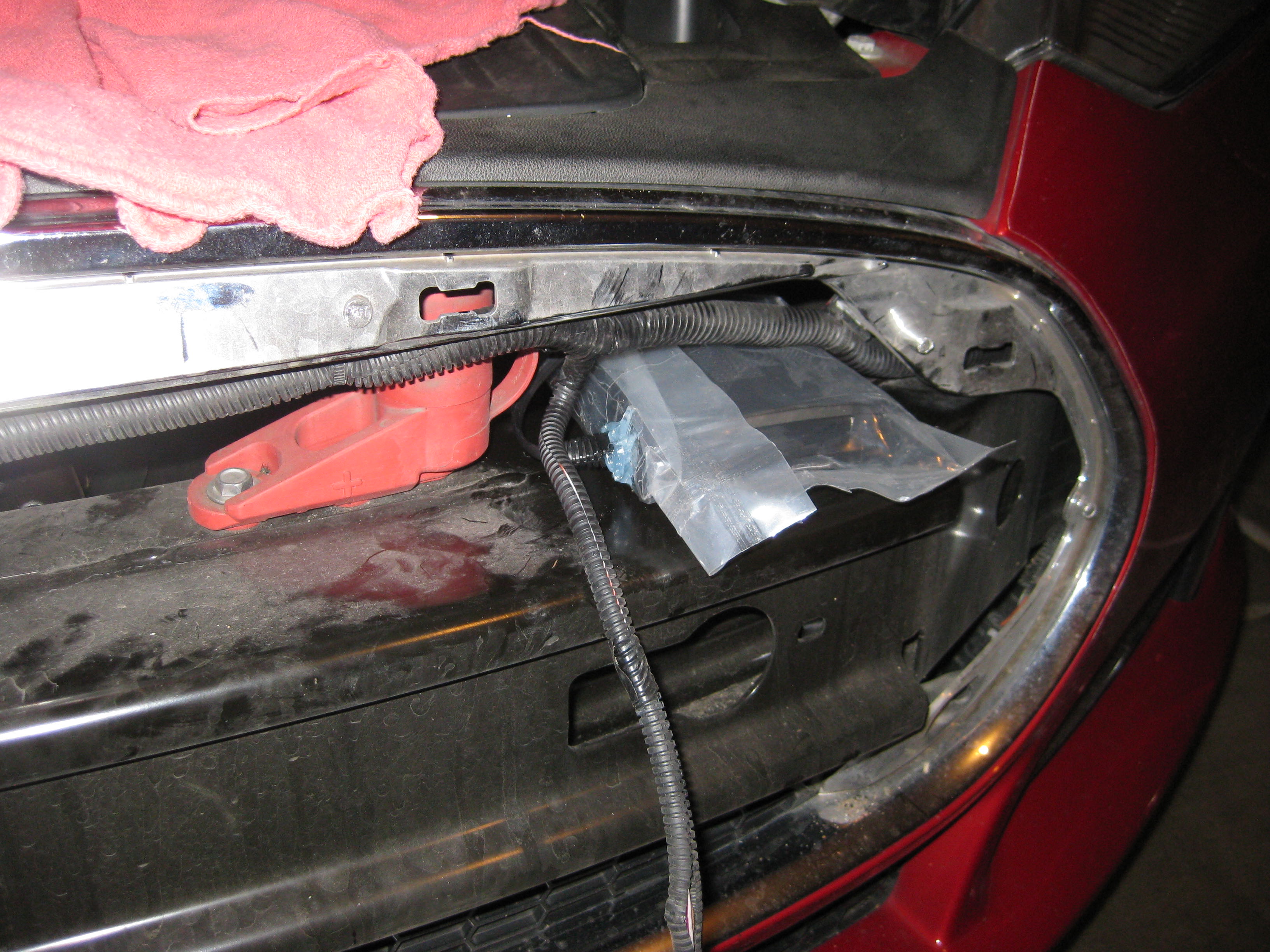
5. Test fit the V1. There needs to be room around the red positive jump post and the negative jump post stud. Otherwise, the sharp teeth on jumper cables can easily damage the bag and expose the V1 to water later. If the vehicle is equipped with Homelink, don't block the Homelink module. On my Homelink-equipped car, the far driver's side and far passenger's side were the best options. I figured that the driver's side is closer to the center of the road and will theoretically have better range for oncoming radar and radar in the same lane. Putting the V1 where the Homelink module location is likely the best choice for cars without Homelink.
6. If the V1 is going to be installed toward the driver's side of the car, remove the driver's side underhood apron now. It is removed in the same way as the passenger's side underhood apron that was removed earlier.
2. Poke a small hole in the bag, directly in front of the data/power inlet. Use scissors and/or a precision knife (such as X-Acto) to enlarge the hole just enough to fit the phone cord connector.
3. Retain the piece of bag material that was cut for later use, or, if there is excess material at the edge of the bag that can be cut without losing the seal function, cut off a section of the excess and retain it for use in a later step.
4. Now that the bag is no longer air-tight, fold over any excess bag toward the top of the V1 and use sturdy waterproof tape to wrap the excess bag material tight. Make sure that the bag is tight all around the V1. If this step isn't performed, the bag will be tightly sealed to the car but the V1 will slide around in the bag with each turn and stop.
5. Test fit the V1. There needs to be room around the red positive jump post and the negative jump post stud. Otherwise, the sharp teeth on jumper cables can easily damage the bag and expose the V1 to water later. If the vehicle is equipped with Homelink, don't block the Homelink module. On my Homelink-equipped car, the far driver's side and far passenger's side were the best options. I figured that the driver's side is closer to the center of the road and will theoretically have better range for oncoming radar and radar in the same lane. Putting the V1 where the Homelink module location is likely the best choice for cars without Homelink.
6. If the V1 is going to be installed toward the driver's side of the car, remove the driver's side underhood apron now. It is removed in the same way as the passenger's side underhood apron that was removed earlier.
Functional test
1. Connect the V1 power/data cable (phone cord) to the appropriate port on the Direct-wire Power Adapter.
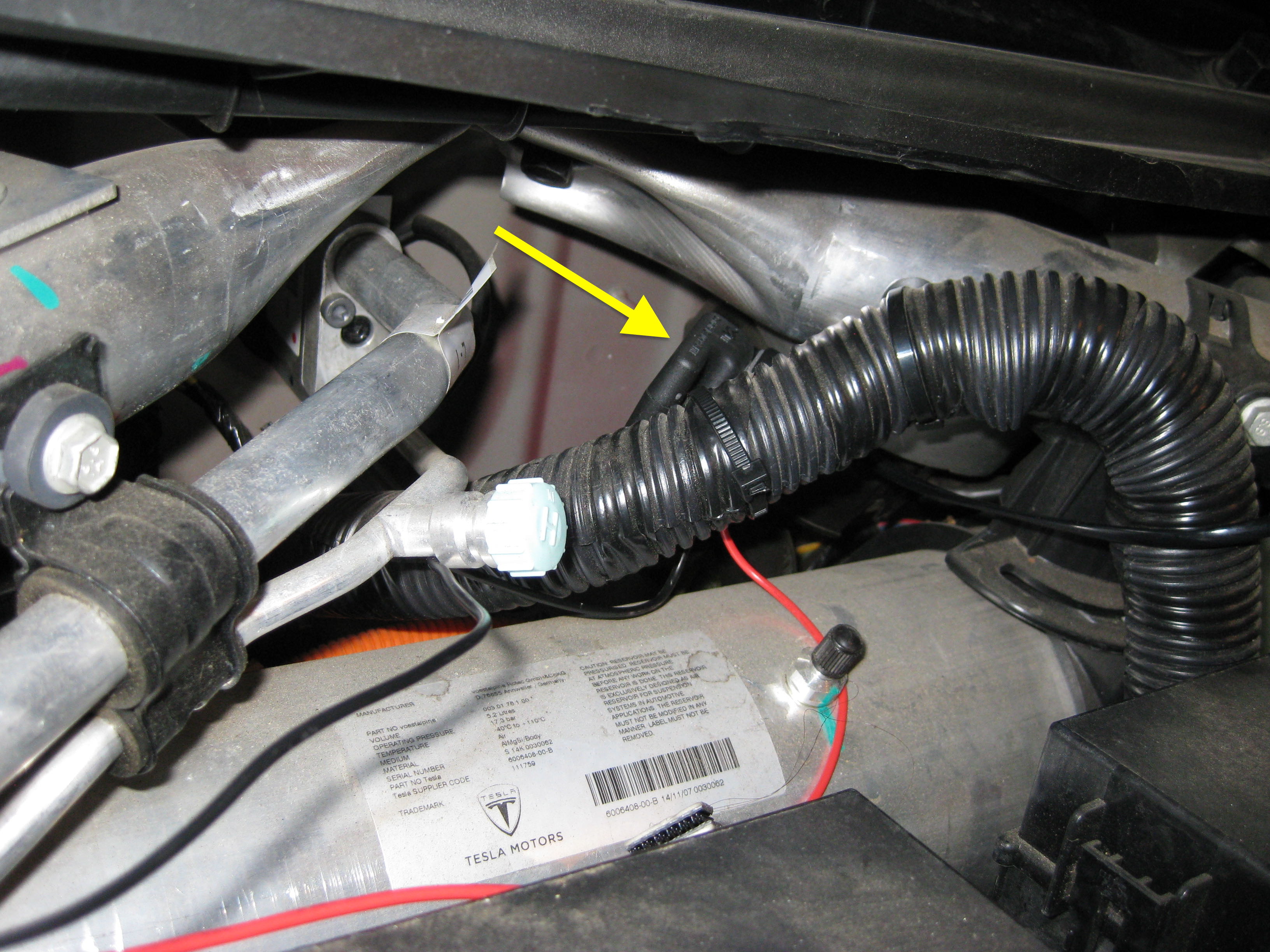
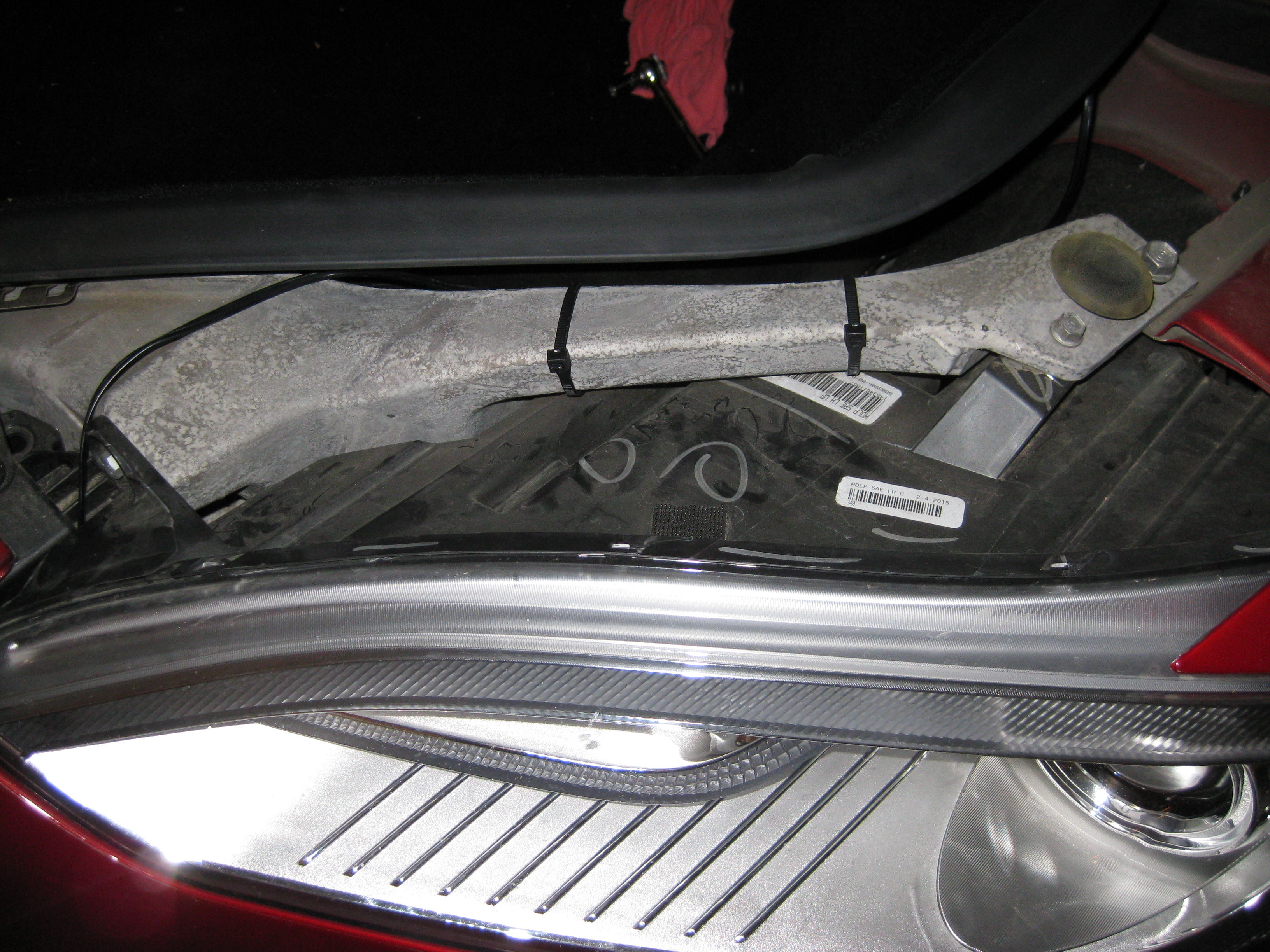
2. Route the V1 power/data cable through the gap inboard of the driver's side headlight. Note: This is the best place to route the power/data cable on my configuration. Vehicles with the composite (black plastic) front carrier might have different places to route the cable.
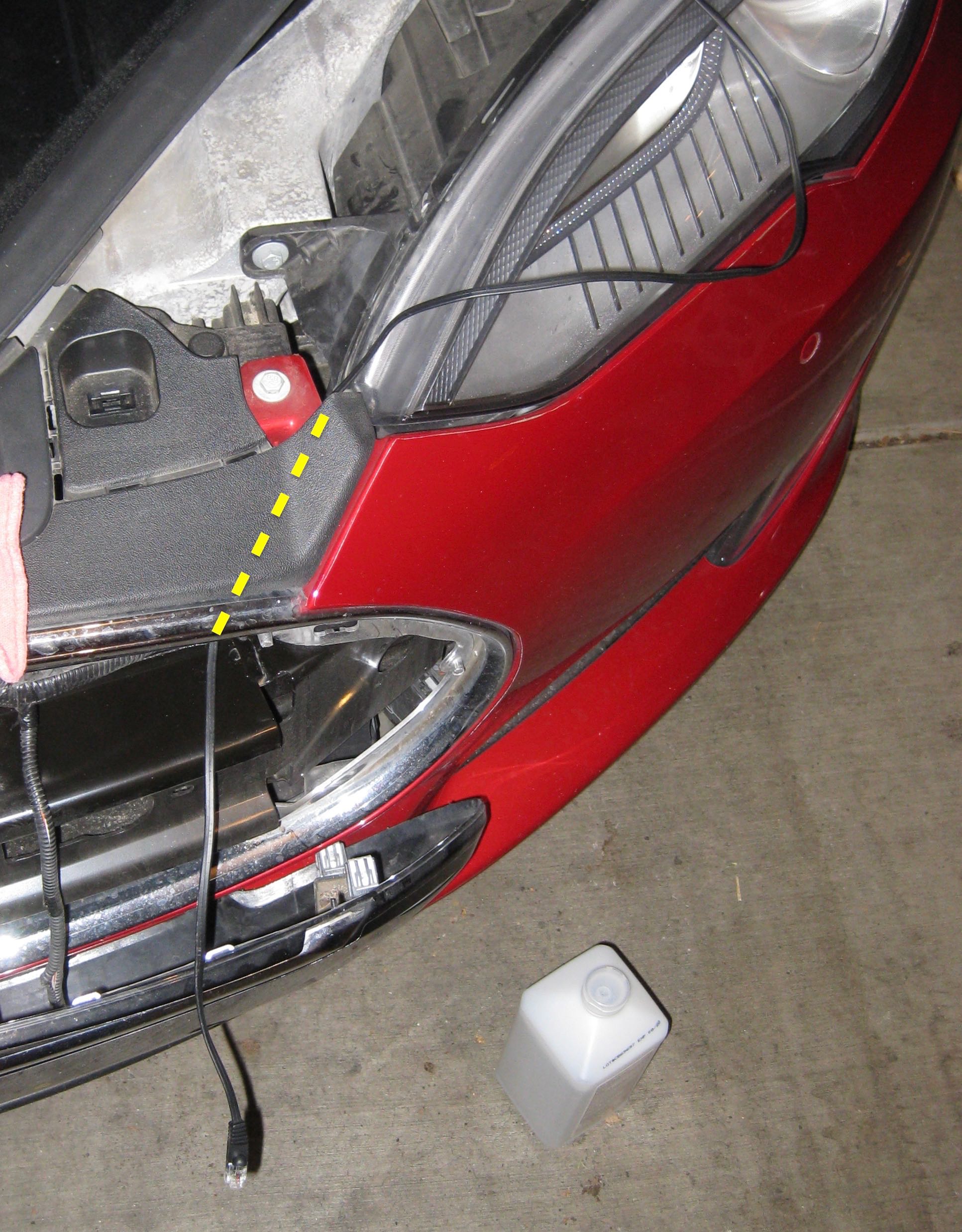
3. Pull the power/data cable through and connect it to the V1. Pull on the connector to confirm that it is secure.
Leave some extra slack in the V1 power/data cable at this time.
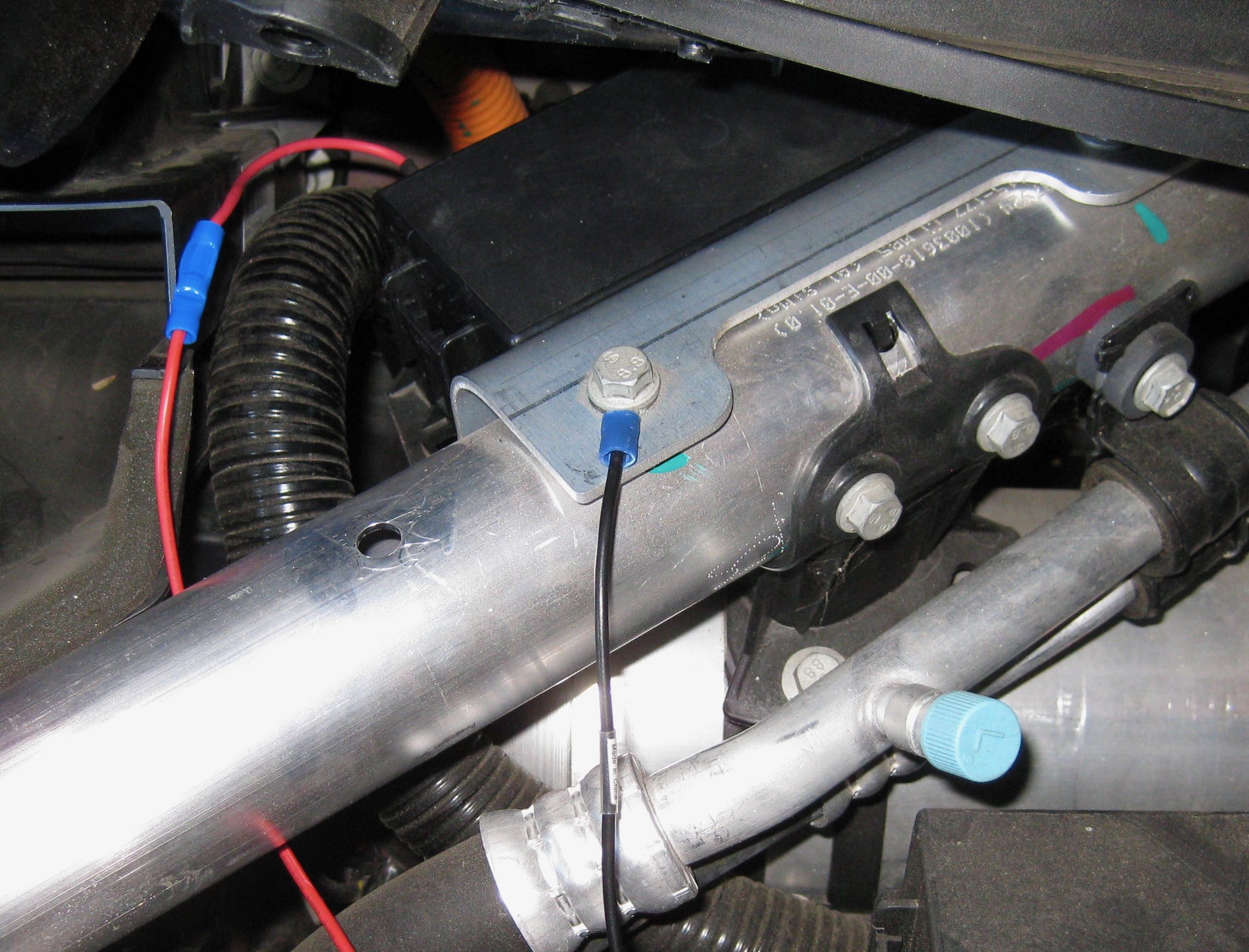
4. I don't remember what kind of terminal originally came attached to the black V1 power adapter ground cable. If necessary, cut off the terminal on the end of the ground cable and crimp on a "stud" terminal (looks like a U) or another terminal that is appropriate to place under one of the bolts that secures the fusebox bracket to the diagonal brace.
5. Loosen one of the bolts that secures the fusebox bracket to the diagonal brace, insert the stud connector on the end of the black V1 ground cable under the bolt head, and re-tighten it.
6. Clean the top of the Bluetooth module and the top of the V1 Direct-wire Power Adapter with rubbing alcohol and let them dry completely.
7. Use double-sided foam tape to affix the Bluetooth module to the V1 Direct-wire Power Adapter. Follow the tape instructions for applying pressure to the tape.
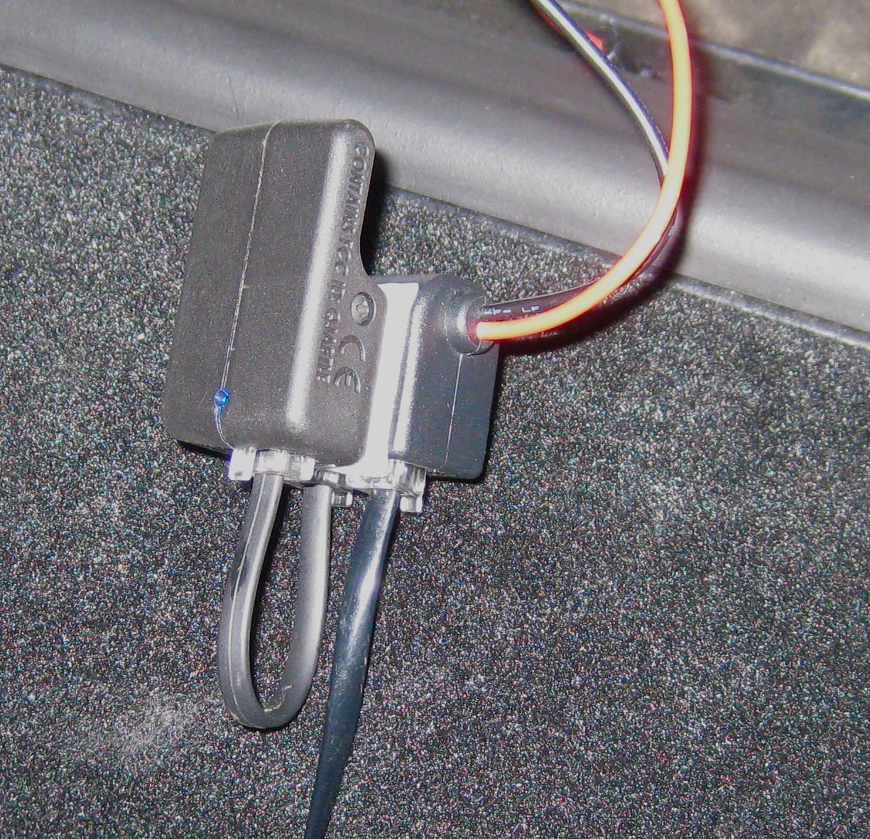
8. Use the short V1 power/data cable to connect the Direct-wire Power Adapter to the Bluetooth module.
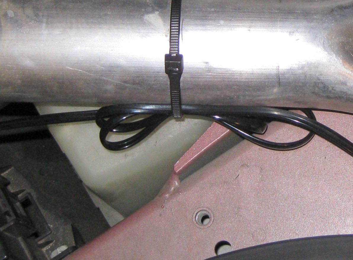
9. Use a cable tie to secure the newly-created Bluetooth/Direct-wire Power Adapter assembly to the back of the wiring loom adjacent to the the driver's side diagonal brace. Position the assembly so the Bluetooth module is facing the bulkhead. Make sure that the assembly is tight and cannot touch the diagonal brace or the nearby air conditioning pipes.
Note: This Bluetooth module location was adequate for an iPhone 5 in most positions in and near the center console; start with this position for now, but be aware that you might need to move it later.
10. Cut off the connector on the end of the red V1 power cable.
11. Strip a segment of insulation from the end of the red V1 power cable.
Important: Slip a piece of heat-shrink tubing over the red V1 power cable.
12. Crimp the red V1 power cable to the butt connector that is already attached to the fuse tap.
Note: Do not heat the heat-shrink tubing yet.
13. Sit in the driver's seat and close the door.
14. Turn on the smartphone that will be used with the vehicle.
15. Press the brake pedal.
16. Open the V1Connection app. Check to see that the V1 is recognized and the Bluetooth strength is good when the phone is positioned where it will be located during normal driving.
2. Route the V1 power/data cable through the gap inboard of the driver's side headlight. Note: This is the best place to route the power/data cable on my configuration. Vehicles with the composite (black plastic) front carrier might have different places to route the cable.
3. Pull the power/data cable through and connect it to the V1. Pull on the connector to confirm that it is secure.
Leave some extra slack in the V1 power/data cable at this time.
4. I don't remember what kind of terminal originally came attached to the black V1 power adapter ground cable. If necessary, cut off the terminal on the end of the ground cable and crimp on a "stud" terminal (looks like a U) or another terminal that is appropriate to place under one of the bolts that secures the fusebox bracket to the diagonal brace.
5. Loosen one of the bolts that secures the fusebox bracket to the diagonal brace, insert the stud connector on the end of the black V1 ground cable under the bolt head, and re-tighten it.
6. Clean the top of the Bluetooth module and the top of the V1 Direct-wire Power Adapter with rubbing alcohol and let them dry completely.
7. Use double-sided foam tape to affix the Bluetooth module to the V1 Direct-wire Power Adapter. Follow the tape instructions for applying pressure to the tape.
8. Use the short V1 power/data cable to connect the Direct-wire Power Adapter to the Bluetooth module.
9. Use a cable tie to secure the newly-created Bluetooth/Direct-wire Power Adapter assembly to the back of the wiring loom adjacent to the the driver's side diagonal brace. Position the assembly so the Bluetooth module is facing the bulkhead. Make sure that the assembly is tight and cannot touch the diagonal brace or the nearby air conditioning pipes.
Note: This Bluetooth module location was adequate for an iPhone 5 in most positions in and near the center console; start with this position for now, but be aware that you might need to move it later.
10. Cut off the connector on the end of the red V1 power cable.
11. Strip a segment of insulation from the end of the red V1 power cable.
Important: Slip a piece of heat-shrink tubing over the red V1 power cable.
12. Crimp the red V1 power cable to the butt connector that is already attached to the fuse tap.
Note: Do not heat the heat-shrink tubing yet.
13. Sit in the driver's seat and close the door.
14. Turn on the smartphone that will be used with the vehicle.
15. Press the brake pedal.
16. Open the V1Connection app. Check to see that the V1 is recognized and the Bluetooth strength is good when the phone is positioned where it will be located during normal driving.
If the V1 is not recognized, check:
- Phone has Bluetooth turned on
- Blue light on the V1 Bluetooth module is on
- V1 power and ground cables are properly connected
- V1 volume knob is on
- Fuse tap is fully seated
- Bluetooth module phone cable and V1 phone cable are in the correct ports (the ports aren't interchangeable)
- V1 phone cable is connected to the V1
- Move the phone around to see if the signal strength improves. If so, the Bluetooth module will need to be moved closer to the phone.
V1 mounting
1. Apply sealant to the test pieces of bag material that were cut off earlier. Check that the bag doesn't immediately react (disintegrating, melting, distorting) when sealant is applied.
2. Wait at least 15 minutes for the sealant to harden, then re-check the bag material for compatibility with the sealant.
3. Apply sealant to the power/data cable connection at the V1. Make sure that the area is completely sealed, with no gaps. This just needs to be functional, not beautiful. If necessary, use a clean tool (such as a flat-blade screwdriver) to smooth out the sealant and shape it.
4. Allow the sealant to harden for at least 20 minutes (check the packaging for instructions). The sealant does not need to be fully cured, but it does need to be stiff enough to completely hold its shape when the V1 and cable are handled in the next steps. Hardening time depends on temperature and humidity (high humidity causes the sealant to dry faster).
5. Clean the bottom of the V1 bag and the top of the bumper beam thoroughly with rubbing alcohol. Allow to dry completely before continuing.
6. Apply 2 strips of foam tape to the bottom of the V1 bag in the locations shown (this avoids putting foam tape over the seam on the top of the bumper beam, which would weaken the adhesion). Follow the tape instructions for applying pressure to the tape.
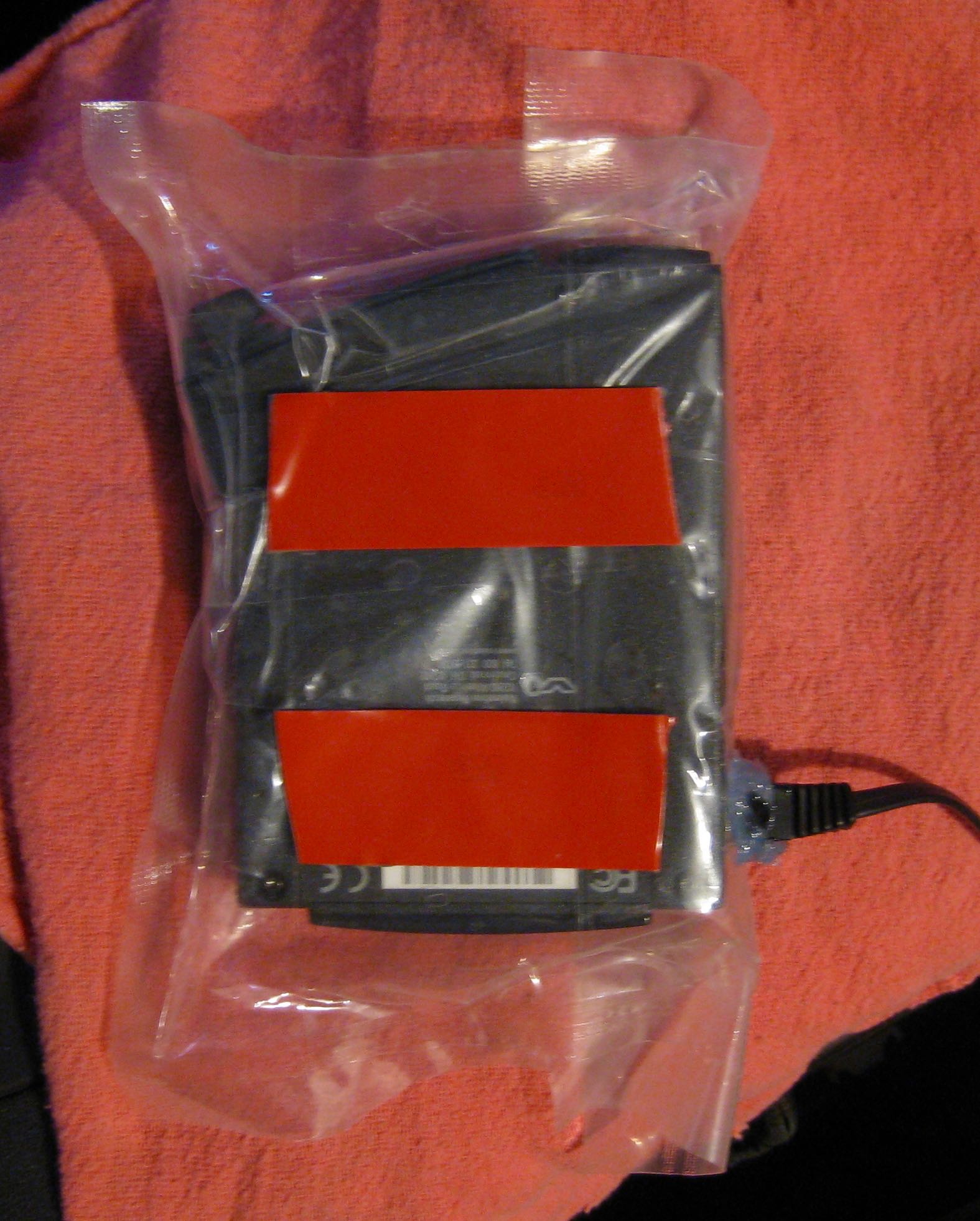
7. Make one last check of the V1 volume knob (on, but turned down low).
8. The next step requires attention to multiple things at the same time, and you only get one try. Review all of these tips first, and try a practice run before removing the backing film from the foam tape:
10. Now that you're mentally prepared, remove the backing film from the double-sided foam tape, and install the V1 on the bumper beam.
11. Follow the tape instructions for applying pressure to the tape.
2. Wait at least 15 minutes for the sealant to harden, then re-check the bag material for compatibility with the sealant.
3. Apply sealant to the power/data cable connection at the V1. Make sure that the area is completely sealed, with no gaps. This just needs to be functional, not beautiful. If necessary, use a clean tool (such as a flat-blade screwdriver) to smooth out the sealant and shape it.
4. Allow the sealant to harden for at least 20 minutes (check the packaging for instructions). The sealant does not need to be fully cured, but it does need to be stiff enough to completely hold its shape when the V1 and cable are handled in the next steps. Hardening time depends on temperature and humidity (high humidity causes the sealant to dry faster).
5. Clean the bottom of the V1 bag and the top of the bumper beam thoroughly with rubbing alcohol. Allow to dry completely before continuing.
6. Apply 2 strips of foam tape to the bottom of the V1 bag in the locations shown (this avoids putting foam tape over the seam on the top of the bumper beam, which would weaken the adhesion). Follow the tape instructions for applying pressure to the tape.
7. Make one last check of the V1 volume knob (on, but turned down low).
8. The next step requires attention to multiple things at the same time, and you only get one try. Review all of these tips first, and try a practice run before removing the backing film from the foam tape:
- The V1 must face as close to straight ahead as possible. Ignore the bumper beam and the bumper cover--they are not straight at all. Face the car and look up at the windshield, roof, bodyside, and overall shape of the car. Make the long (straight) part of the V1 body perfectly perpendicular to the overall length of the car.
- Make sure the V1 knob is pointed toward the back of the car (in other words, the power/data cable is toward the front of the car).
- Don't bump the V1 knob.
- Keep the V1 as high as possible. Push up on the park assist sensor harness (if equipped) for extra wiggle room.
- Don't let the tape touch the bumper beam until the V1 is positioned properly!
- The front of the V1 should not overhang the bumper beam. It's ok if the loose edge of the bag does a little; it will fold up if it touches the nosecone.
10. Now that you're mentally prepared, remove the backing film from the double-sided foam tape, and install the V1 on the bumper beam.
11. Follow the tape instructions for applying pressure to the tape.
Securing the cables
1. Use cable ties to secure all of the V1 hardwire kit components and cables. Here are some important tips:
- Even electric cars vibrate like crazy as the tires roll over imperfect pavement. Noise from vibrating cables or parts near the front bumper probably won't be heard inside, but vibrating cables or parts near the bulkhead will be maddening and difficult to track down.
- Cable ties are ideal for securing cables and small parts to existing wiring harnesses and hard parts. Make sure the cable ties are tight to prevent vibration. Closely space the cable ties to prevent movement of the cables.
- The frunk tub is removed during many vehicle services, so don't attach cables to the frunk tub or do anything that would require extra steps to remove the frunk tub in the future.
- Don't block the HVAC filter housing or 12V battery, which is directly below it on the rear wheel drive nosecone cars.
- Don't let the wires touch anything especially hot or cold (such as the air conditioning lines that are near the diagonal brace).
- Don't position the cables or components where they will interfere with the underhood aprons.
- The magnesium front carrier doesn't allow the power/data cable to be well-secured near the headlight. As mentioned previously, this shouldn't be a big NVH issue since the cable is lightweight and it's far from the cabin. The composite carrier might allow the cable to be better secured.
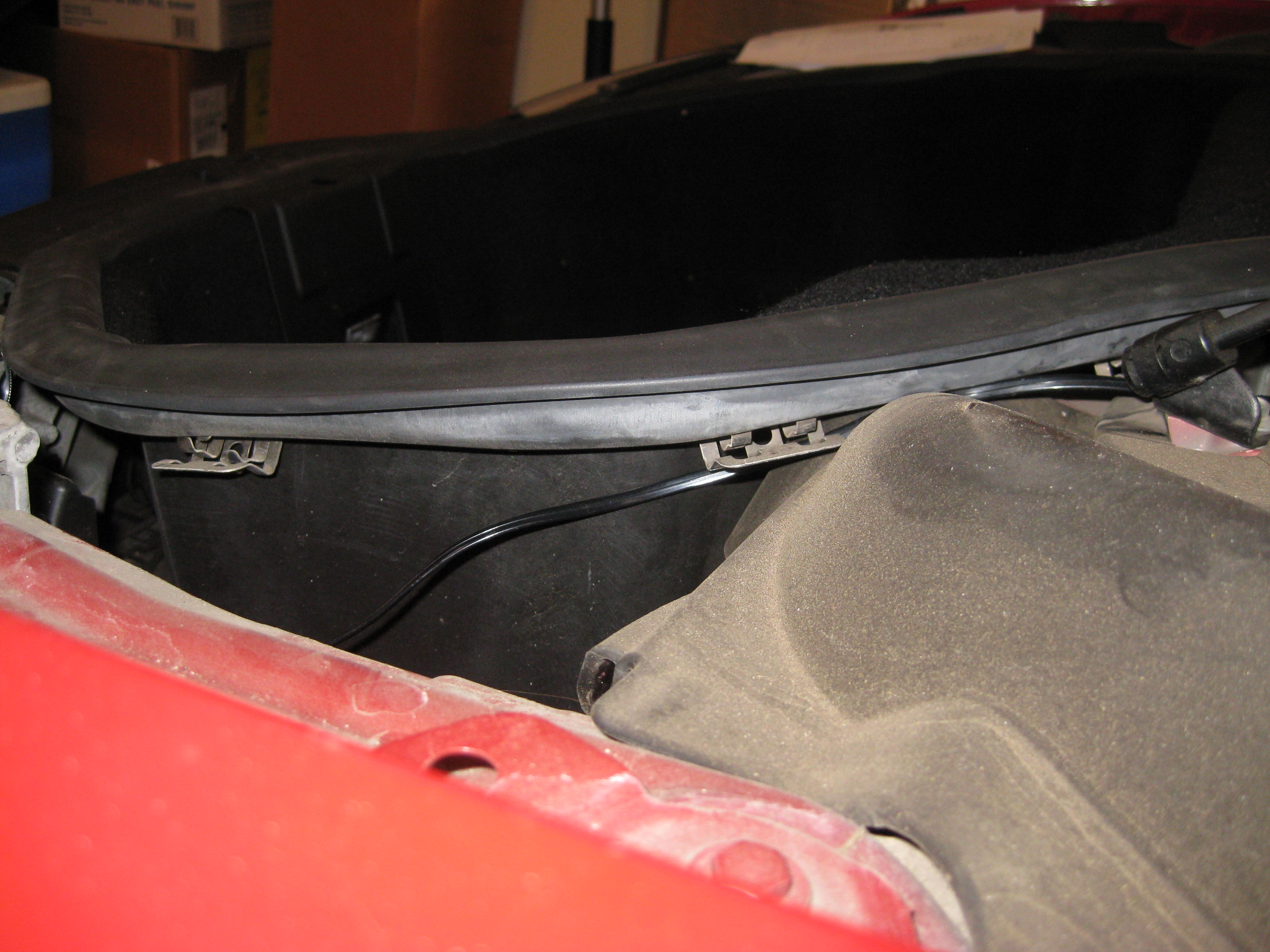
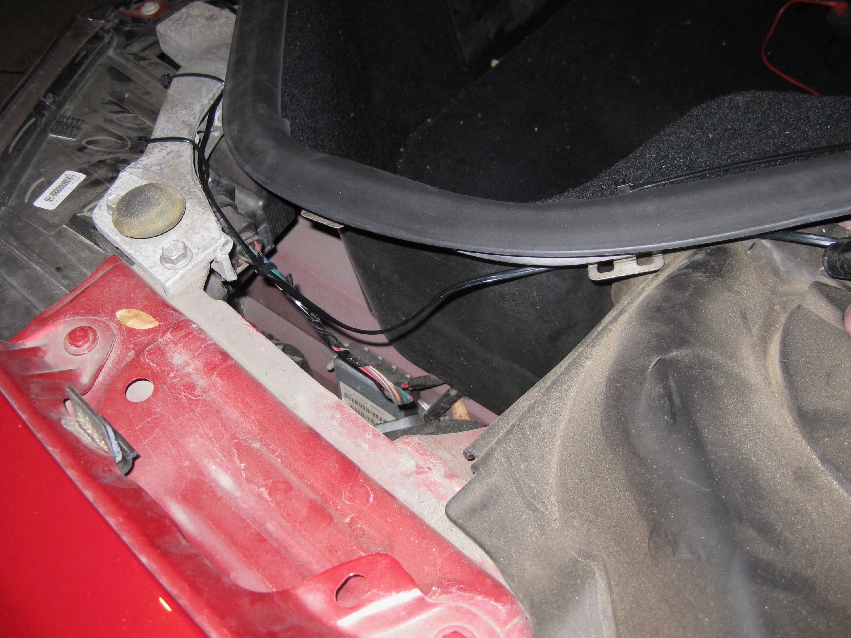
- The frunk tub has metal clips on the sides that are used to support the driver's side and passenger's side underhood aprons. Route the power/data cable under these clips.
- There's no good place to secure the power/data cable near the side of the frunk tub.
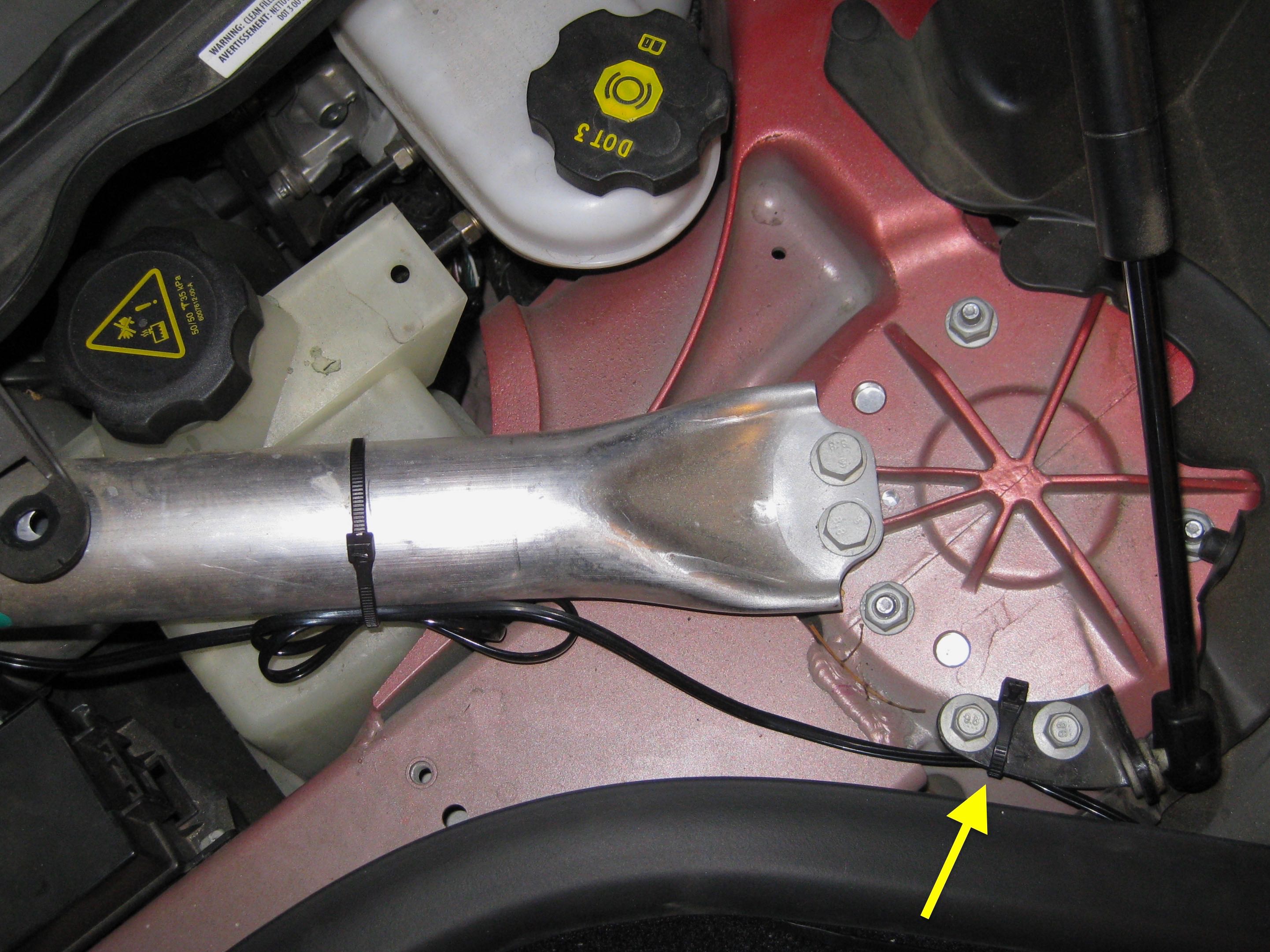
- Use a cable tie to secure the power/data cable to the mounting bracket for the hood lift strut.
- There is likely to be excess power/data cable and potentially excess red and black V1 power and data cables. Make a bundle with the excess and secure the bundle with a cable tie in a location where it won't interfere with trim panels or anything mechanical.
- If there's a chance that a cable or component could touch a part of the car, wrap it with open-cell foam weatherstripping. You can get this at a home improvement store. If the part ends up touching something, the weatherstripping will keep it from making noise.
- If you want to look extra-professional, the wires could all be covered in small-diameter corrugated loom. If this was in the underhood area of a conventional car, I would recommend it, but here they're not exposed to excessive heat, moisture, or vibration, so it would be just for cosmetics...but the only people to ever see them are technicians repairing the car.
Reassembly
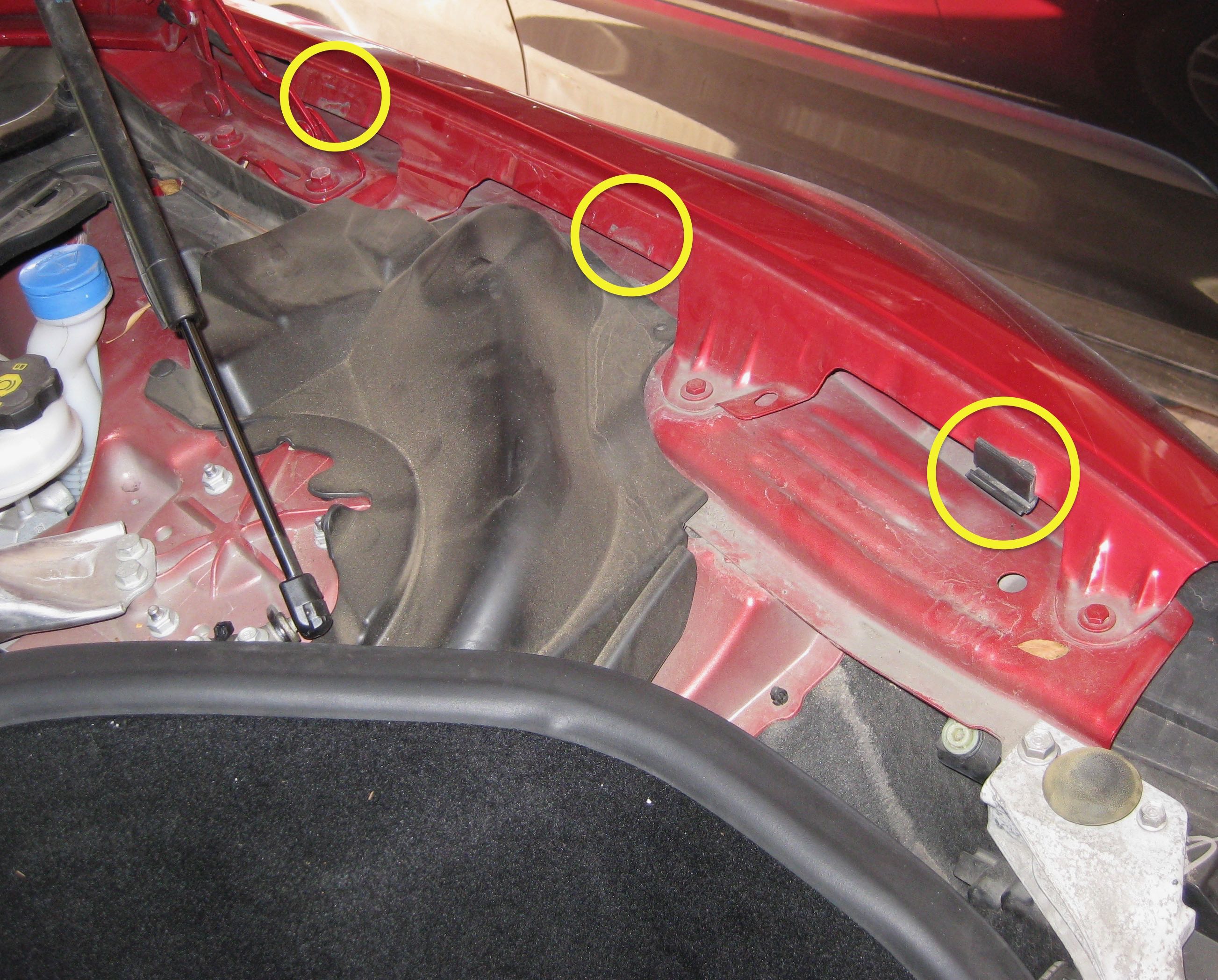
1. Check the driver's side and passenger's side underhood aprons. On my car, several clips came off when the side underhood aprons were removed. Round plastic push clips can be easily slid back into place. Hook-shaped clips were originally secured to the fender with double-sided foam tape (luckily we've got plenty of it on-hand and know how to use it):
2. Twist the cowl screen panel back into its normal position.
3. Install the 3 push pin rivets that secure the cowl screen panel (remember, 1 rivet hole is hidden under the flexible rubber shock tower cover).
4. Install the HVAC filter front housing, if you removed it.
5. Install the HVAC filter with the airflow arrow pointing up.
6. Install the driver's side and passenger's side underhood aprons. Pull the edges of the rubber bumpers through the holes in the aprons. Use a flat blade screwdriver to pry the edges of the rubber bumpers into position, if necessary.
7. Install the rear underhood apron.
8. Check all underhood aprons for flushness. They are built with some flexibility; it might be necessary to push and pull on them to get the slots in one panel to line up with the tabs in another.
9. Reconnect the parking sensors on the nosecone, if applicable.
10. Reinstall the nosecone.
11. Sit in the driver's seat and press the brake pedal.
12. Turn off Jack Mode.
- Hold the hook-shaped clip in a vise or with locking pliers (such as Vise-Grips) and use a razor, utility knife, or scraper to remove as much of the old tape as possible. Warning: Don't try to hold the clip in your hand while using a razor or utility knife. You can really hurt yourself.
- Look at the opposite side of the car and/or the dirty spots on the edge of the fender to figure out where the clips should be attached. Clean the fender and the clip surfaces with rubbing alcohol, let them dry completely, and then reattach the clips using double-sided foam tape.
2. Twist the cowl screen panel back into its normal position.
3. Install the 3 push pin rivets that secure the cowl screen panel (remember, 1 rivet hole is hidden under the flexible rubber shock tower cover).
4. Install the HVAC filter front housing, if you removed it.
5. Install the HVAC filter with the airflow arrow pointing up.
6. Install the driver's side and passenger's side underhood aprons. Pull the edges of the rubber bumpers through the holes in the aprons. Use a flat blade screwdriver to pry the edges of the rubber bumpers into position, if necessary.
7. Install the rear underhood apron.
8. Check all underhood aprons for flushness. They are built with some flexibility; it might be necessary to push and pull on them to get the slots in one panel to line up with the tabs in another.
9. Reconnect the parking sensors on the nosecone, if applicable.
10. Reinstall the nosecone.
11. Sit in the driver's seat and press the brake pedal.
12. Turn off Jack Mode.
Test drive
Go for a test drive. If you're already a V1 user and you're using Valentine's V1Connection app, the interface will look very familiar, but 3rd party apps will require some familiarization. Drive past some known false signals in your neighborhood to get a feel for how the app responds.
I've had my V1 installed this way for close to 2 years now, with no problems. Good luck!
