Welcome to Tesla Motors Club
Discuss Tesla's Model S, Model 3, Model X, Model Y, Cybertruck, Roadster and More.
Register

Disappointing Power Generation, and I need help with analysis of pypowerwall output please!

This site may earn commission on affiliate links.
@solarpics Are you seeing the reduced generation in the Tesla app and in pypowerwall? I can't quite tell from your posts. Do the numbers match between the app and the api?

If they're both missing the data from the second inverter I'm wondering if it's even hooked up correctly or turned on. Pypowerwall talks to the Gateway and the Gateway should pull the data from both inverters.
There is no hard data line between the gateway and the standalone inverter that is why pypowerwall cannot pull the string level data from a stand alone inverter. Of course the gateway will be able to monitor the power flow from that inverter via the solar CT.
 
There is no hard data line between the gateway and the standalone inverter that is why pypowerwall cannot pull the string level data from a stand alone inverter. Of course the gateway will be able to monitor the power flow from that inverter via the solar CT.

Interesting. I have two Powerwall+ so I can see all my strings. Strange that Tesla doesn't talk to the standalone inverters the same way.
 
I'm no expert and just guessing here. Looking at the 3 line diagram, I thought MP2 and MP5 are parallel into (4) and goes into inverter 2. MP4 itself in series into (6) and MP1 and MP3 parallel into (5) and into inverter + GW making it 3 strings only. So coming down from the junction box there would be (4), (5) and (6) in the diagram and the V mp and Imp of (4), (5) and (6) would be the max DC, no?
That is exactly what I figured as well, thanks for the confirmation.
 
I believe based on the wiring diagram that string A is not connected since strings B, C, and D closely match what the wiring diagram shows. I assume that it is just floating to the -1.2V with nothing connected to it but don't have any direct experience here.

There is no way to get the standalone inverter data from pypowerwall to my knowledge. I have two standalone inverters and would love to get the real time data on the strings. They only way to get the data is to power cycle the inverter, connect to the inverter's wifi access point, and then point your browser to 192.168.92.1. This is only possible withing 15 minutes of power cycling the inverter. The issue I had which may be particular to my setup is that it took 15 minutes for the inverter to fully come online and find the maximum power points for my strings so the data I got was not useful.
I also tried what you mentioned a few weeks ago (power cycling the standalone inverter, and I was able to connect to it via browser and 192.168.2.1. I recall it came online after a couple of minutes (2 or 3?), but stayed online for only about 15 minutes. It was very annoying and time consuming, and I hated to power cycle the inverter just so I can get a few minutes of readout. Maybe I will try that again since I've learned a lot from everyone here over the last few days. Thanks again!
 
I have a 7.5kw SunPower microinverter system, interior California, at nearly the same latitude as San Jose. Mostly southwest/west facing so a better orientation, but I produce 45-50kwh/day right now. I find it hard to believe that a properly functioning 10kw system, even one with suboptimal panel orientation, couldn’t do significantly better than that.
Thanks for the feedback, I agree, I think output is low on mine. My PVWatts calculations matches Tesla's "commitment", and the actual performance for June is about 30% below this. Time to go argue with Tesla again!
 
You might be able to at least isolate the total output of the standalone inverter. For example, in your 11am data from above, the combined string power from the larger inverter is 2321+925+828=4074W. That seems close to the expected output based on your PVWatts plots (mp1+mp3+mp4=~4.5kW). What was the total solar output at that time (based on either pypowerwall or the Tesla app)? If you subtract the larger inverter output from the total output, you'll get the standalone inverter output. Based on your PVWatts plots, you should expect ~2kW at 11am (mp2+mp5).
Nice call! The Tesla App GUI shows 4.8kWh at 11:00AM Monday. Does this mean the standalone inverter's output (MP2+MP5) was 726Wh? Both the app and pypowerwall I think should reflect all the string outputs. But all of this is very confusing so I'm not sure.

For the PVWatts plot I picked a random/typical day in June that appeared to be cloudless (i.e. smooth curve) and had good output, but it wasn't the highest output.
 
Last edited:
@solarpics Are you seeing the reduced generation in the Tesla app and in pypowerwall? I can't quite tell from your posts. Do the numbers match between the app and the api?

If they're both missing the data from the second inverter I'm wondering if it's even hooked up correctly or turned on. Pypowerwall talks to the Gateway and the Gateway should pull the data from both inverters.
No, pypowerwall and the Tesla App don't match. I just checked 11:00AM Monday pypowerwall vs Tesla App, and the difference was 726Wh. Is this difference the output of the standalone inverter? I'm getting very confused.
 
Last edited:
  • Like
Reactions: jgleigh
Of course the gateway will be able to monitor the power flow from that inverter via the solar CT.
This makes sense. So if there is a Powerwall and standalone inverter in a system like mine, the App has to combine the data from the solar CT and from the Powerwall to get accurate power information. So the 726Wh that I calculated in my previous posts could indeed be the standalone inverter's output (which is MP2+MP5).
 
  • Like
Reactions: jgleigh
The Powerwall+ will also have a CT to monitor solar production, but also talks to the Gateway over a data connection so you can get the detailed battery and string data. The standalone inverters only have the CT for monitoring solar and no data connection back to the Gateway.

If you open the covers on the two inverters you should see the CT modules (little black box with a CT clamp around the inverter outputs).

Is the total output as reported in the Tesla app closer to what you calculated on PVWatts?
At 11:25AM this morning, this is what I measured:

Tesla App = 5.0 kW
pypowerwall (B+C+D) = 2.285+0.930+0.831 = 4.046 kW
PVWatts (July 1) = 6.1 kW

So the Tesla App reports a value closer to PVWatts than pypowerwall, but still definitely lower.

Thanks for the info on the CT; for some reason I thought the CT's were elsewhere in the circuit (i.e. not in the inverter box). I took photos of the PW Inverter (first pic below) and the standalone inverter (second pic). Is the black module in the first pic the CT? I didn't see anything similar in the standalone inverter.

20220701_093807.jpg
20220701_093736.jpg
 
At 11:25AM this morning, this is what I measured:

Tesla App = 5.0 kW
pypowerwall (B+C+D) = 2.285+0.930+0.831 = 4.046 kW
PVWatts (July 1) = 6.1 kW

So the Tesla App reports a value closer to PVWatts than pypowerwall, but still definitely lower.

Thanks for the info on the CT; for some reason I thought the CT's were elsewhere in the circuit (i.e. not in the inverter box). I took photos of the PW Inverter (first pic below) and the standalone inverter (second pic). Is the black module in the first pic the CT? I didn't see anything similar in the standalone inverter.

View attachment 823625View attachment 823624
I thought CT is supposed to be a ring clamp thing, mine is in the load center where I have my house breaker, inverter breaker and PW breaker. Mine is not the same as yours but here are pictures showing where the CT is in the load center and where it is plugged into in the GW2.
 

Attachments

  • Load Center.jpg
    Load Center.jpg
    379.7 KB · Views: 68
  • GW2.jpg
    GW2.jpg
    403.6 KB · Views: 61
I thought CT is supposed to be a ring clamp thing, mine is in the load center where I have my house breaker, inverter breaker and PW breaker. Mine is not the same as yours but here are pictures showing where the CT is in the load center and where it is plugged into in the GW2.
CT in Gateway.jpg

Thanks, you're correct. I opened my gateway and found it (it appears gray in the photo, but it's actually black - this was taken in bright sun).
 
View attachment 823757
Thanks, you're correct. I opened my gateway and found it (it appears gray in the photo, but it's actually black - this was taken in bright sun).
That's the CT monitoring the standalone inverter. I would hazard a guess that the PW+ integrated inverter does not have a standard CT clamp and instead uses the electronics within the inverter itself to monitor the power produced.
 
That's the CT monitoring the standalone inverter. I would hazard a guess that the PW+ integrated inverter does not have a standard CT clamp and instead uses the electronics within the inverter itself to monitor the power produced.
I agree with this - I didn't see anything in the PW+ inverter that looked like the CT in the GW, and it would make sense that Tesla wouldn't put one into the PW+ inverter since the functionality is already there.
 
The CT clamp for the PW+ will be tucked into the upper left corner around either the blue or yellow wires. You can see the lead coming out the top of the Neurio box (little black box). I can't quite see it in your picture but it'll be tucked back in there somewhere.

It looks like everything is hooked up correctly, so your generation might be lower for other reasons (shading, etc).
You are correct, the PW+ CT is indeed in the upper left corner, I had to move the wires aside and peek behind it, but it's there!

Regarding shading, I've been taking a close watch on the two strings attached to the standalone inverter, and your theory was correct - MP5 is shaded at 2PM. It's on the garage roof, and at 2PM, the sun is behind the house so the second story throws a shadow on MP5. If I "zero out" MP5 in pypowerwall from 2PM to evening, this will cause a hit of 4kW on a cloudless day, which brings the "estimate" for the entire array down to 54kW (which is still 10kW less than what I get). Regarding the other string connected to the standalone inverter, MP2 is high on the 2nd story roof, with nary a tree or shadow-throwing structure in sight (my neighbor's house is about 15 feet from mine, and same height. There are no trees here).

Thanks for all your help!
 
  • Like
Reactions: jgleigh
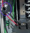
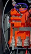
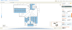
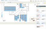
I got Tesla on chat this morning, and they were able to email the drawings right away! Here are the pertinent pages. I was wrong about a couple of things. There are actually 5 strings as shown in the drawings, not 4. I was also off regarding the roof pitch. Of the 5 strings, MP2 and MP5 are connected in parallel, MP1 and MP3 are connected in parallel, and MP4 is connected serially. See the third sheet below.

View attachment 821974
View attachment 821975
View attachment 821976

This is the string data from pypowerwall taken at 11:00AM this morning, which is close to what PVWatts says is peak power time:

String Data: {
'A': {'Current': 0.0, 'Voltage': -1.1999999999999993, 'Power': 0.0, 'State': 'PV_Active', 'Connected': False},
'B': {'Current': 12.77, 'Voltage': 183.5, 'Power': 2321.0, 'State': 'PV_Active', 'Connected': True},
'C': {'Current': 4.51, 'Voltage': 206.3, 'Power': 925.0, 'State': 'PV_Active', 'Connected': True},
'D': {'Current': 4.05, 'Voltage': 205.8, 'Power': 828.0, 'State': 'PV_Active_Parallel', 'Connected': True}}

I think String B is MP1+MP3 due to its high current, but not sure about String C and D.

After getting the schematics, used the actual pitch and azimuth for all five strings and input them into PVWatts (5 times, one for each string), downloaded the hourly results, compiled them, and got these numbers:

PVWattsActual% difference
Annual Production (kWh)12846N/AN/A
June total month production (kWh)1644N/AN/A
June average daily production (kWh). Full month for PVWatts, 6/1-6/26 for Actual54.840.95
-33.8%​
June highest 24 hour production (kWh)61.647.6
-29.4%​
June peak instantaneous output (kW)6.985.5
-26.9%​

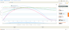
I'm including a plot of the June 14 performance, which appears to be typical of a clear sunny day. Output was 58.2kWh for the entire day, peak was 6.54kW at noon.
View attachment 821946View attachment 821947

Does anyone have any additional thoughts about this? I know it's a lot of information. But so far all performance measurements I've made are consistently ~30% below what is expected based on PVWatts. This seems pretty bad. If the low performance is caused by a bad installation, I'm not sure what to tell Tesla without identifying exactly what they should look at.

Thanks!
The string terminated to the wrong MPPT on the inverter (12 Amp max per MPPT port).
The 10 panels (1x5,1x5) connected parallel (37.5x5 ~ 185 V) should be terminated at the jumper port 4 (split the current to 2 MPPT) and the serial 6 panels (1x6) (37.5x6~ 206V) should be on port 2.

String Data: {
'A': {'Current': 0.0, 'Voltage': -1.1999999999999993, 'Power': 0.0, 'State': 'PV_Active', 'Connected': False},
'B': {'Current': 12.77, 'Voltage': 183.5, 'Power': 2321.0, 'State': 'PV_Active', 'Connected': True}, this parallel string should connect to the jumper C and D
'C': {'Current': 4.51, 'Voltage': 206.3, 'Power': 925.0, 'State': 'PV_Active', 'Connected': True},
'D': {'Current': 4.05, 'Voltage': 205.8, 'Power': 828.0, 'State': 'PV_Active_Parallel', 'Connected': True}}

Cheer