Welcome to Tesla Motors Club
Discuss Tesla's Model S, Model 3, Model X, Model Y, Cybertruck, Roadster and More.
Register
This site may earn commission on affiliate links.
Check the youtube channel I started about DIY repair of the Tesla Large Drive Unit (DU).
This may benefit those who like to fix their car themselves, epecially if it's out of warranty.

Here is the link: https://youtube.com/channel/UCIHg1trfQQTYIA88w-ZcCdw

Background: The DU in my 2012 Toyota RAV4 EV started to leak coolant internally. This DU is very similar to single rear motor in Tesla Model S, but with reversed gear teeth and an added parking brake mechanism. The Mercedes Benz B class Electric Drive has the same DU as RAV4 except differences in the electronics hardware. A special thanks to QC Charge who tought me a lot through their Youtube videos and Schenkzoola's experience at the RAV4 EV forum.
 
Cool!
I leased MD B class for three years while waiting for M3 (could not get my wife out of our MS). It was great little car. Initially, I wanted RAV4 but it was not available in my state. It's great to see that people are still driving these cars. And fixing them.
 
Discussion about this topic can become very long and spread over multiple threads, forums, youtube, etc, making it difficult to find the info you need. @howardc64 and I created an info directory (a website) dedicated to this LDU, especially the coolant leak problem. It contains links to rebuilds by multiple individuals and also a list of past and current seal longevity experiences, torque specs, etc.

Dirctory link: Tesla LDU
 
  • Like
Reactions: snoltor and TheFro
Can anyone recommend a good time to do any kind of preventative care or modification? I have a 2013 P85 with 140k miles. LDU sounds great but I worry about it's longevity (along with the HV battery) and I want to so what ever I can to prevent any issues down the road. If there's anyone in Texas that can do this kind of work, let me know.
 
First baby step on Tesla LDU removal. Jacking up the car.

3x jacks, 2x jack stand, ceder 4x4x8 (stronger than fir), car ramps, and some misc pieces of wood got both rear tires off on jack stand and car leveled. Need to do it in 2 lifting phases

1. Raise the rear tires onto about 6" of wood with 2 jacks on the rear lift pads. Pull the belly cover (Tesla calls it mid aero shield). If only want to check speed sensor for coolant leaks. This is sufficient lift.

2. Raise front tire onto car ramps with 2 jacks on the front lift pads (I personally don't like driving up the metal ramps. Too accident prone)

3. Put 2x4 over both rear lift pad and 4x4x8 ceder beam across the bottom. Offset the 2 jacks outside of the lift pad area under the 4x4 leaving enough space for jack stands. Lift up and and place jack stands directly under 4x4 below the lift pads. 4x4 will bow a little and will hear wood creaking sounds (maybe the 2x4 under the jack pad are getting pressed pretty good) so a 3rd jack in the center of the beam is helpful to keep the 4x4 relatively straight. Go slow and raise a little on the side jacks followed by the center jack and alternate.

The subframe does look like have a relatively flat area on each side for jack and additional flat jack surfaces after removing rear skid plate. I didn't use this but just pointing out.

Bought a motorcycle jack which goes from 5.5" to 19.5" to drop the LDU+subframe. 14" drop maybe just enough space. If not, will raise the 4x4 beam slightly after LDU+subframe is dropped. Will post pic afterwards.
 

Attachments

  • IMG_2530.jpeg
    IMG_2530.jpeg
    417 KB · Views: 2,670
  • IMG_2524.jpeg
    IMG_2524.jpeg
    387.3 KB · Views: 456
  • IMG_2529 (1).jpeg
    IMG_2529 (1).jpeg
    330.3 KB · Views: 416
  • 68455869466__3A264787-628E-49B3-951E-19FE3B23136E.jpeg
    68455869466__3A264787-628E-49B3-951E-19FE3B23136E.jpeg
    372.6 KB · Views: 414
  • IMG_2531.jpeg
    IMG_2531.jpeg
    432.2 KB · Views: 441
Last edited:
An update on putting rear up on jack stands.

Removing the rear skid plate/bar reveals a nice flat area on the subframe to place jacks.

IMG_2539.jpeg

However, it is still desirable to use a cross beam + 2 jacks for lifting as shown in previous post. The reason is as follows

- Once subframe is dropping, the jack point is lost. If the subframe lowering jig doesn't provide enough clearance to get it out. Will be necessary to jack up the rear end to increase clearance. My motorcycle jack provided 14" clearance. Needed another 1 inch (by jacking up the 4x4 cedar cross beam) to clear the subframe+LDU from under the car.
 
Last edited:
  • Like
Reactions: Droschke and vanR
Dropped the subframe+LDU tonight. Here are the tips to supplement missing info in the Tesla service manual

POST #1 (picture attach limit per post so need to break up the posts)

Disconnecting the Parking Brake connector

Tesla service manual calls for this step but after dropping the subframe+LDU on my 2013 MS85, was completely unnecessary. Pic below shows the whole parking brake wiring harness came down with the subframe so completely unnecessary to disconnect the connector (PITA)

IMG_2571.jpeg

If you have some reason to disconnect parking brake. Do passenger side first (red release tab easier to get to, driver side is harder to reach). The red tab (red will show after removing all the dirt) need to be popped open with a flat tip screw driver and can actually be fully removed. Both tab and connector are hard to remove due to dirt build up. Have to find various angles to tap the tab off and leverage the connector off (evenly lever off multiple sides a little bit at a time to avoid breaking the lock tab mechanism)

IMG_2536.jpegIMG_2537.jpegIMG_2538.jpegIMG_2534.jpegIMG_2533.jpeg

The parking brake is engaged and locked so the rotor is not going to turn. Don't know if this will be an issue. Even if need to turn the rotors, the parking brake motor can be easily removed and brake released.

Disconnecting parking brake connector may create more room to help remove the drive axle later.

Disconnect 4 connectors in rear of subframe (12-13 MS only?)

I pried all 4 connectors out of the subframe and 1 XMAS tree securing the wiring harness. Probably best leave the XMAS tree in so wiring harness is tucked close to the subframe. There isn't much clearance in front and rear of the subframe when dropping it. Probably easy to damage these connectors and wiring hardness. I believe these are related on 2014+ cars. Probably after Tesla saw numerous damages.

Probably worth prying out the 4 connectors from subframe. Read later section on carefully dropping the subframe to avoid damaging wiring harness.

HV bolt port housing

My B+ port had a cutout. Thought it was broken first but looked like designed that way to avoid damaging o-ring when inserting the cover

IMG_2566.jpeg

Release the clips that secure HV Cables

Here is what they look like and the tool I use to get under them to release them. Very tight space

IMG_2562.jpegIMG_2563.jpeg
 
Last edited:
  • Like
Reactions: Droschke and vanR
Post #2

Draining Coolant

Good to clamp the hose to avoid draining excess coolant from rest of the system. Use hose clamps (I had vice grips combined with some rubber pads). I then plugged the hose with a plastic cap and rubber stopper (hose is ~3/4 ID, I believe the rubber stopper I used was #3 with 15/16" on the large end diameter). Also use 2 buckets to catch both inlet and outlet as more will drain after opening both up. Not too much coolant came out of LDU (I did spill a little) After draining, capped it with dish washing rubber glove cut finger tips and zip tied for security (Avoid making a mess on rest of the subframe steps)

Might also route the driver side hose upwards on the side of the subframe so it doesn't get in the way during the drop.

IMG_2545.jpegIMG_2546.jpegIMG_2544.jpeg

Draining the Gear Oil

About 1.5qt total. Both my drain and fill magnetic plug had some mud on it (30k mile total on the LDU)

IMG_2556.jpeg

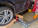
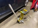
Dropping the Subframe 3 inches

Need to drop 3 inches to gain access to release the HV cable from the inverter, HV cable bracket, and grounding wire. I used the motorcycle jack for this purpose. Removed the top jack platform for greater stability. Center of gravity is heavier on the motor side (driver side) so need to offset the jack accordingly.

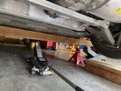
Used a thick plastic binder sheet to protect the rear subframe wiring harness during the drop. There is barely any clearance in front and rear of the subframe to exit. And the chassis screw tabs for the mid aero shield can be easily smashed in the front of subframe (subframe actually need to move 1/2 cm backwards to clear) and damage the wiring harness in the rear.

I pulled the 2 passenger side wiring harness connectors to clear any body/frame pinch points. I pushed the 2 driver side wiring harness connector above the subframe beam to be safe during the drop.

Furthermore, motorcycle jacks do not drop vertically, it will angle forward as it drops. So I repeated the following steps

- pull subframe towards back of the car to provide 1/2" clearance in front of the subframe from the mid aero shield tab (thought about cutting it off haha) Check the rear subframe harness is safe (will gain clearance as motorcycle jack drops)
- lower subframe 1/2 inch.
- repeat

IMG_2568.jpegIMG_2567.jpegIMG_2570.jpegIMG_2550.jpeg

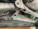
Remove the shock mount bolt

After 3-4 inch drop, can knock out this bolt with a hammer and a short (2-3”) 1/4” ratchet/socket extension).

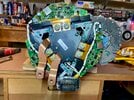
Releasing the HV Cables

Cables are secured to the inverter casing with a black plastic clip with 4 fingers that grab at evenly space 90 degrees. Release the fingers 1 at a time and pull that side of the clip slightly upwards. Then rotate 90 degrees to get the next finger. Need to release all 4 fingers to pull up the black plastic clip completely. Then a big flat head should be able to pry up the wire from the housing if you don't have salted roads or flooded car. Another person helping to pull back the wheel liner is helpful to create more space and remove the sharp liner edge pressed against the arm.

I labeled on of the cables (B-) to avoid mixing them up later

IMG_2574 (1).jpeg

Dropping subframe all the way

I did this in a couple of phases. Each phase 3-4 inches with additional stands for safety (jack stands under subframe locations, some wood below the plywood on motor cycle jack) just to ensure motorcycle jack could handle the weight and balance. Once I got the motor cycle jack in proper center of gravity (bias towards driver side where the heavier motor is), the control was quite good.

Initially, I had the motor cycle jack centered on the centerline of the car and subframe was leaning to driver side during the drop. Use a jack under driver side control arm to lift up that side of the subframe. Dropped the whole subframe plywood assembly onto wooden standing blocks (2 4x6s stacked on each side of the jack) Shifted jack toward driver side and found center of gravity and balance)

Don't forget to drop 1/2" at a time while pulling the jack backwards 1/2" until front/rear of the subframe and the wiring harness clears the bottom of the car chassis. 2 people is really helpful in this process. One to control the jack, the other to spot front and rear subframe clearance.

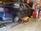
Jacking up the car 1-2 inch to clear the subframe+LDU from under the car

My motor cycle jack provided 14" of lift. With the 1/2" plywood and 2x4 padding blocks, needed another 1-2 inches to clear the bottom of the car. Put the jacks on each side of the cross beam that was used to put car on jack stands to gain the necessary clearance.

IMG_2572.jpeg
 
Last edited:
One more update on dropping the subframe.

I used a plywood sheet that is 27" wide as a platform above the motorcycle jack. This didn't provide enough space for 2 floor jacks (lifting pad will also move away from front wheel when lowering) with a (wood) cross beam on the side (with motorcycle jack in between) to provide vertical drop without lateral movement (floor jacks handles ~4-5" drop while motorcycle jack does the rest and can wheel it out from under the car) Wider plywood could work but will hit the lower control arm if go too far. Below are probably ideal dimensions

- 22" x 31" 1/2" (maybe 2 sheets?) or 3/4" plywood. 31" max between lower control arms. 22" between front and rear subframe cross beam.
- 4x (22"-26") 2x4 (or 2x 2x4 + 1x 4x4) on top of the plywood to mate up against the 3 cross beams on the subframe. Center of the cross beams are welded and inset so not flush with the outer edges of the cross beam. Therefore, the 2x4/4x4s need to be long enough to contact outer ends of the cross beam.
- Center 2x4 should be placed midpoint between 22" length of plywood to match the middle subframe cross beam.

IMG_2542 (1).jpeg
 
  • Like
Reactions: vanR and Droschke
Pulled the DU out. I did the following to avoid damage while puling DU

- Remove the coolant neck on the motor side (plastic and close to subframe)
- Remove the speed sensor (plastic)
- Remove the coolant tube on top (avoid any damage from lifting harness)
- Watch the inverter plug plastic housing carefully. Very close to the subframe and have seen damage pics presumably from pulling DU

68513428270__079C89F5-33A2-48AE-AA31-2CB547129A09.jpegIMG_2582.jpegIMG_2583.jpegIMG_2584.jpegIMG_2588.jpeg68514896844__B0BBA11B-D7AE-4EAD-AF77-E08A9B4A14EE.jpeg68515018681__5E5F7561-4D91-481B-ABA0-A9418D3B93E0.jpeg
 
  • Like
Reactions: vanR and Droschke
Unfortunately, I have corrosion inside the inverter. Car drives fine, only decided to check speed sensor and found coolant at 30k miles after install. Can't seen to see any coolant trail coming from the tunnel to the motor and along the bottom of inverter casing. Perhaps it doesn't leave any. Here is another post showing no clear coolant trail from motor side at the lowest spot (along the rectangular connector and B+ B- bolt holes.


Another possibility is leak in the inverter coolant channels itself but no clear evidence.

68515090575__F2E76FB6-BC5D-45AD-B1BC-8DEDC6BC43E1.jpegIMG_2603.jpegIMG_2594.jpegIMG_2595.jpeg

Looks like a grounding strip and a bundle of white wires near the inverter connector started wicking some coolant. The electronics behind the connector is like entombed in clear plastic for protection so that probably saved it.

IMG_2606.jpegIMG_2596.jpegIMG_2600.jpegIMG_2608.jpegIMG_2609.jpeg

Anyway, tapping a drain seem paramount in the inverter. Perhaps a couple on each end on the bottom of the casing.

Another valuable mod would be change that black plastic piece for the B+ B- terminal to clear. Then any leak in that area is easily visible without removing the LDU. This requires manufacturing of course.

BTW, there is a somewhat easy test to check inverter leak. Just pull the inverter connector cover. My cover had tiny drops of coolant and inside the B+ B- bolt housing looked a bit dirty. But of course B+ B- are HV so need to be cautious with HV protection one is comfortable with.
 

Attachments

  • IMG_2607.jpeg
    IMG_2607.jpeg
    473.5 KB · Views: 448
Last edited:
UPDATE on inverter coolant intrusion.

The bottom seam between the inverter casing and gearbox housing is sticky for about 6" along the circumference. This is the clearest evidence coolant came from the motor side through the bus bar tunnel and collected and condensed there. This is good news because it says most likely no leak along inverter's internal coolant channels :)

So clean it all up (got rid of big chunks but can't rid of all beauty marks, I figure steel wool would be a bad idea near the circuit boards and IGBTs haha) and off to chase down the leak on the motor side...

IMG_2610.jpegIMG_2611.jpegIMG_2614.jpeg
 
Last edited:
  • Informative
Reactions: Droschke and Krash
Question - were there any symptoms that made you believe the DU was leaking coolant internally? I have a P90D with the factory single seal, and all these recent failure threads have my worried (and i'm not sure if it's warranted).

Some threads claim they will all fail, and replacements will fail too. Others say "there are thousands of cars with hundreds of thousands of miles on their original drive unit."

Mine drives just fine, no weird symptoms that i'm aware of, but curious what signs come up that make you think "hmm, maybe im leaking."

My Rev Q reman LDU was installed in 2017 at 40k miles (now 72k mi so I do 6k/year). My had a light whine under certain conditions since the beginning and new higher pitch noise at all speeds recently. But most people don't notice. I seem to be good at picking up slightest sound changes.

Saw the thread to pull speed sensor to check for coolant so checked and bingo... coolant. Did a bunch of research (seal design, material, application, contacted seal manufacturers etc.). My conclusion is no seal is going to keep really low viscosity and slippery coolant from leaking beyond few 10k miles in this application. All seals in traditional cars prevent much thicker oil from leaking. Completely different than trying to keep coolant from leaking. This design is probably beyond what is possible. Tesla tried changing deal design and seemingly only got worse.

Regarding failure rate and why there is more noise now.. I think its because 2012-14 Model S's are coming off warranty honeymoon. Most LDU cars has had multiple LDUs under Tesla's 8 year unlimited mile warranty (Mine was 3rd at 40k miles) so no one cared. Most car's LDUs were getting swapped out by Tesla every few 10k miles. My guess is Tesla saw plenty seal leaks and made effort to change them without success. Now warranty honeymoon is over, next LDU change cost is on the owner and quite expensive... thus, the increase in thread traffic. 2015s starts coming off 8 year warranty in 2023 so noise is probably going to continually increase.

Don't know if P90D has the coolant cooled induction LDU in the rear. If so, best check annually and my guess is need to plan on seal change say every 30k miles. Non Tesla rebuilders are adding drain modifications to keep the collateral damage down. These might last longer before self destruct. Tesla still installing the same problematic design.

Note > 100k mile battery failures are not uncommon so some people get the double whammy as thread traffic shows. So we really have 2 big $$$ maintenance risk at ~8+ year mark.

How do we know which LDUs are liquid cooled? I thought they are were.