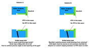
Coolant Air Bleed
Most of the air bled out during initial power up, plug-in charger and then firmware update (which just rebooted the car). Some combination of repeatedly disconnecting power and/or repeatedly plug/unplug charging would perform this initial bleed
How to bleed air out of coolant on Tesla model S - YouTube
Note on the power dis/reconnect sequence. It isn't clear on the reconnect order.
Disconnect : 12V negative first, fireman's loop next
Reconnect : Tesla service manual just says "reverse". Above video reconnects fireman's loop followed by 12V negative. I did 12V negative and fireman's loop on initial power up after LDU reinstall. Seen that done somewhere and figure it was safer.
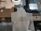
After initial bleed which consumed majority of the 2-3L of lost coolant during LDU rebuild. Another 3 drive cycles for total of 1+ hour slowly bled out the remainder air and stablized. One natural worry is... is the lowered coolant going into the LDU? Its unlikely to have that much leak without LDU having some problems. If tapped a drain on bottom of motor end plate (pic 1&2 on this
link) and inverter housing, then can be more sure.
Coolant Leak Scare
After installing rebuild LDU on the car, found a wet patch (not a puddle) on the floor next morning And felt dampness below the coolant manifold. This was due to 1 or maybe 2 factors
- Wet patch was probably leftover splashed coolant when connecting the car's coolant inlet hose to the LDU coolant manifold. Despite cleaning up, the car is then taken off the jack stands. Test driven a couple of times. Ample opportunity for any coolant hiding around the area to drop to the floor.
- Originally tightened the bottom 2 bolts on the coolant manifold to 4Nm which isn't very tight at all. Guessing may have had a very small leak despite the o-ring and the sealant. Of course the dampness could also be from the splashed coolant as its the lowest spot.
Cleaned up the wet patch and tightened the bottom 2 coolant manifold bolts (just snug tight with a small 1/4" ratchet. probably 8-10Nm) Now its all dry below the coolant manifold after 90 miles of driving and nothing on the garage floor for 2 days.
Routing the drain tube
Clear silicon drain tube from the reluctor chamber drain tap can be routed externally for easy sight glass coolant leak inspection
- Loop around coolant inlet hose and secure with a zip tie to reduce pulling load on the tube and drain barb fitting
- Cut a hole to exit the tube and make a loop at the end. Leaked coolant would drain but loop would save some evidence of the leak
Note during early stage of seal leak, not enough coolant will collect and drain. Only way to know is periodic more cumbersome inspection of the speed sensor (raise rear safely, remove a bunch of bolts and screws, 2 fins, aero shield, pull speed sensor)
 LDU Whine Noise Changed Post Rebuild
Downhill regen whine is gone but the faint new whine that started before rebuild is still present.
Changed 5 bearings (2 SKF rotor ceramic, SKF 6208/6207 on primary shaft. FAG intermediate shaft counter bore roller bearing) Only observed damage was 6207's outer race got spun in the bore (post
#47). Perhaps this was the source of downhill whine? Maybe overheated? No idea. New 6207 installed with retaining compound (
post #50) 6207 was installed with retaining compound on an Rev R LDU.
Faint whine starts at 31-32mph during acceleration. 5 new bearings above and 1500mL of Pennzoil Platinum Dex VI compat ATF. The 3 big bearings (2 on differential, 1 on intermediate shaft) was not changed nor anything inside the differential.
LDU was a 2017 Tesla Rev Q rebuild and original manufacturing date in 2013. Perhaps some wear in the differential which probably was not changed on Tesla rebuild. I'd assume Tesla rebuild would have changed out all 6 bearings in the gearbox along with rotor ceramic bearings.
Post Rebuild Analysis
Realized a number of things post rebuild. Unfortunately TMC doesn't allow editing changes of content older than an hour. So here is a list
Temp Sensor Disassembly
Disassemble temp sensor connector. I believe when pulling out the wires in post
#35, some micro plastic stops internally in the connector was likely damaged. During assembly (post
#55), inserting the wire would not click or lock by itself and easily slide out. However, once the blue tab was installed, all the wires are fully locked so its fine. During disassembly, I looked for locking tabs etc (with a magnifying eyewear) that commonly lock these wire in the connector but didn't find a way.
Alternative to disassembling the temp sensor connector is to remove the inverter. This has advantages and disadvantages. Advantage is the ability to assemble the 2 gearbox halves with the inverter off and maybe even vertically with the inverterless half dropping down on the gear set with good control. Disadvantage is reinstalling the inverter and easily damage the coolant o-rings, may need yellow loctite (probably 577 glycol resistant), and additional disassembly of the inverter (post
#51 and #52) . Disassembling the temp sensor is probably a better solution if no other reason to remove the inverter.
Scissor lift car better than motor cycle jack
Scissor lift cart would have been easier than motor cycle jack during LDU+subframe reinstall per post
#62. But cost more of course.
Breather caution on upside down gearbox assembly
If assemble both halves of the gearbox upside down for firmer inverter footing per post
#55, then need to consider any fluids clogging the breather. My gearbox was pretty free of any flowing fluids after long rebuild process.
Testing New Bearings vs old
Testing new bearings is challenging. Ceramic bearings will make noise if rotor is slightly uneven (noted in post
#53). New bearings have factory protection but not lubrication. Adding lubrication will not cover all corners of the open cage ball bearings instantly even if soaked in ATF briefly. Anyway, no matter how careful I was in installing the new bearings, they never seemed smooth as the fully lubricated old bearing when loading radially (hold bearing and tilt shaft at 45 degree angle). But once in car, they are quickly lubricated far better than can be done by hand. Anyway, besides practicing safe bearing installation methods, have to basically trust the manufacturer/distributor gave you a good bearing.
Without knowing this, I spend quite a bit of time retracing my bearing installation steps. Bought a shop press and a second complete set of bearings before realizing the challenge with properly lubricating these open cage bearings.
Shop Press Unnecessary
Shop press is not necessary. Bearing splitter/puller can be used to press in the new 6208. Ceramic bearings can be tapped in by inner race. Coolant seal can be hammered flush with its bore using pipe + adapter.
SKF lock nut different than OEM
SKF lock nut in post
#49 is not a match to LDU's lock nut. External dimension is similar and can use the same SKF tools. But inner diameter is smaller than LDUs.
There is no reason to change this lock nut and can just reuse the original. I just purchased one since it was $5 and was curious.
Coolant seal Installation error prone
Coolant seal installation is error prone and perhaps the most important part of this rebuild for 2 reasons
The seal and shaft are on 2 different part and fairly high precision over the the contact area. Usually, there are 2 scenarios
1. seal bore and shaft are both on the same mechanical part, This provides easy determination on how deep to seat the seal for proper contact on the shaft.
2. seal bore and shaft are not on the same mechanical part. For example half shaft insertion into the axle seal but the axle shaft provide very wide contact area to engage the seal so not much precision required.
Coolant seal and shaft is case #2 with seal nearly as wide as the shaft contact area. Need to measure carefully to know how deep to press in the seal into its bore. Also additional challenge of not folding/damaging an excluder lip on a PTFE seal. Read post
#57 and
#59 and carefully measure and practice the process prior to final assembly.
Aero Undercover front bolt tab unnecessary
This got knocked off due to tiny clearance. However, the aero undercover has a rigid metal bar/plate with 2 other bolts besides the mid point bolt. Furthermore, aero shield has many other bolts securing it. It is quite stiff and the outer lip of battery chassis faces rear ward. So unless planning to break land speed record in reverse or running serious F1 ground effects. This middle bolt and tab is completely unnecessary. Can probably tap a couple of bolt holes if really want to reattach this bolt. 10/2014+ cars may not have this issue with greater clearance from moving the rear subframe wiring harness connectors.


.jpg")