


A Sept. 11, 2014 Tesla patent for controlling an AWD EV includes claims not just for the dual motor configuration of the 85D, but also for a three motor (85T ?) version.
CONTROL SYSTEM FOR AN ALL-WHEEL DRIVE ELECTRIC VEHICLE - Patent application
Not only is there a torque calculator (based upon look-up tables) to determine the split between front and rear, but a traction controller monitoring wheel slip.
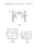
The 9-11 patent doesn't go into details of any sort of sleep or idle mode, but refers to the motors as primary and assist. See the figure 2 for torque and power curves of example motors.
In a preferred embodiment of the invention, one of the two motors is the primary drive motor, e.g., motor 103, while the second motor, e.g., motor 109, is relegated to the role of an assisting motor. Preferably both motors 103 and 109 are AC induction motors. Additionally, in a preferred embodiment assist motor 109 is designed to have a relatively flat torque curve over a wide range of speeds, and therefore is capable of augmenting the output of primary motor 103 at high speeds, specifically in the range in which the torque of primary motor 103 is dropping off. FIGS. 2 and 3 illustrate torque and power curves, respectively, of exemplary motors. In particular, curves 201 and 301 represent the torque and power curves, respectively, of an exemplary primary motor; curves 203 and 303 represent the torque and power curves, respectively, of an exemplary assist motor; and curves 205 and 305 represent the torque and power curves, respectively, of the combination of the exemplary primary and assist motors.
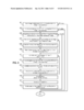
See Figure 8 for the algorithm used to generate the look-up table utilized by the optimal torque split unit;
CONTROL SYSTEM FOR AN ALL-WHEEL DRIVE ELECTRIC VEHICLE - Patent application
Not only is there a torque calculator (based upon look-up tables) to determine the split between front and rear, but a traction controller monitoring wheel slip.
The 9-11 patent doesn't go into details of any sort of sleep or idle mode, but refers to the motors as primary and assist. See the figure 2 for torque and power curves of example motors.
In a preferred embodiment of the invention, one of the two motors is the primary drive motor, e.g., motor 103, while the second motor, e.g., motor 109, is relegated to the role of an assisting motor. Preferably both motors 103 and 109 are AC induction motors. Additionally, in a preferred embodiment assist motor 109 is designed to have a relatively flat torque curve over a wide range of speeds, and therefore is capable of augmenting the output of primary motor 103 at high speeds, specifically in the range in which the torque of primary motor 103 is dropping off. FIGS. 2 and 3 illustrate torque and power curves, respectively, of exemplary motors. In particular, curves 201 and 301 represent the torque and power curves, respectively, of an exemplary primary motor; curves 203 and 303 represent the torque and power curves, respectively, of an exemplary assist motor; and curves 205 and 305 represent the torque and power curves, respectively, of the combination of the exemplary primary and assist motors.
See Figure 8 for the algorithm used to generate the look-up table utilized by the optimal torque split unit;
Attachments
Last edited: