Welcome to Tesla Motors Club
Discuss Tesla's Model S, Model 3, Model X, Model Y, Cybertruck, Roadster and More.
Register

Electrical genius required?

This site may earn commission on affiliate links.
It's an edge case! :) Can't be just volt drop if it doesn't happen with a 9.5 kW shower running and a BMW pulling 32 A on the same circuit as the gate, but does happen with only a Tesla pulling >16 A on a separate circuit. My final report to be submitted to the OP for only £1000/hr looks like...

Causal factors:

Likely combination of undersized/too long cable to gate causing significant voltage drop during motor inrush current, and/or degraded motor, and/or poor condition stiff mechanism requiring high torque to move meaning in normal conditions the motor has only just enough torque to get the gate moving.

In the specific case of a Tesla on charge over 16 A, so it is using two onboard chargers, it injects just enough harmonic distortion to the supply that the motor torque is reduced just enough to stall when operated. Doesn't happen with the BMW cos it has less harmonic distortion, I dunno.

Remedy:

Upgraded underground cable or filtering/isolation, UPS etc for gate.

Bets in.
Alternate Remedy based on your Causal factors:

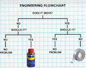
WD40
 
Electrical tape 🙈
Screen_Shot_2014-07-22_at_3.37.29_PM.png
 
For what it’s worth I’ll chuck a Fluke scopemeter across the supply phases, neural and earth when charging over the weekend with Tesla Gen2 wall connector on three phase. It’s never presented any problems over many, many years, but will see just what harmonic shite, if any, it’s passing back to the supply.

I’m still bemused that this should be some esoteric but widespread RF noise / harmonic distortion issue problem - why is affecting just one chap with a gate that doesn’t want to open on a VERY long (unproven gauge & unknown provenance) connection. My bets still on the latter.
Oooh real data! And what DOES the supply look like when the Tesla is charging?

@GPDP did you find out any more. I read through this whole thread but it just came to a dead end.......
need .... to know ...... answer ........

My tuppence is that it will be harmonic interference. Or maybe radio frequency interference.
Without knowing the waveform of the interference this looks about right to fix it:
Schaffner Power Filter
Theres probably cheaper fixes too, but then it costs money to look for them.
 
  • Like
Reactions: ACarneiro
Oooh real data! And what DOES the supply look like when the Tesla is charging?

@GPDP did you find out any more. I read through this whole thread but it just came to a dead end.......
need .... to know ...... answer ........

My tuppence is that it will be harmonic interference. Or maybe radio frequency interference.
Without knowing the waveform of the interference this looks about right to fix it:
Schaffner Power Filter
Theres probably cheaper fixes too, but then it costs money to look for them.
Good reminder 😅 Some data to be gotten tomorrow hopefully.
 
Oooh real data! And what DOES the supply look like when the Tesla is charging?

@GPDP did you find out any more. I read through this whole thread but it just came to a dead end.......
need .... to know ...... answer ........

My tuppence is that it will be harmonic interference. Or maybe radio frequency interference.
Without knowing the waveform of the interference this looks about right to fix it:
Schaffner Power Filter
Theres probably cheaper fixes too, but then it costs money to look for them.
Circling back. I did actually put a DSO scope on the output of the breaker feeding the Tesla Wall Connector - before and after. Perhaps I should've taken some screen shots from the scope screen, but when I ran a harmonic analysis whilst it was running it was remarkably (and not unexpectedly) very clean when measuring the harmonics.

I'll take another look hopefully on Wednesday when I have a bit more time and see if I can work out a THD figure (and get some screen shots from the scope).
Ye I figured they will have cleaned it up a lot, or multiple chargers would distort the local grid too easily, The frequency plot of voltage distortion would be ideal.
 
Ye I figured they will have cleaned it up a lot, or multiple chargers would distort the local grid too easily, The frequency plot of voltage distortion would be ideal.
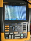
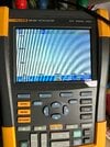
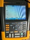
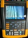
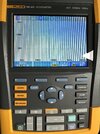
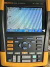
Output of the RCBO to the Gen 2 wall box with 3-phase connection, on each respective phases in the frequency domain.

1. The ‘before’ screen shots taken about half an hour ago. Car *not* plugged in / charging:

A8EEA0EC-4141-4A70-8336-E5DFD35FB3B7.jpeg1BDB3F08-7A23-4C03-BD64-9D9922D557D7.jpegF8CA98ED-F501-4270-9C2D-153085BF2900.jpeg

2. Whilst the car was connected and charging:

D05518D6-D863-4FB6-AC2F-66364E04B956.jpeg436A8BF2-CBF3-42EA-B9DE-E19D28FF0BEA.jpegC729D333-2A77-46E9-A1FB-DC8A69E93054.jpeg

As you can see the before and during charge is virtually identical with very small 1st and 2nd harmonics at 250 Hz and 350 Hz

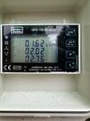
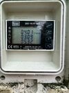
This unit is also metered through a separate TE/Crompton DRS-100-3 MID-compliant meter with THD% measurement - it’s showing dynamic readings like this for THD whilst on charge:

671AFD72-51ED-48BD-9225-F4499193B2FB.jpeg

About the worst I saw on the meter was:
DB8DBC0E-7984-4640-A7DF-79E631018FCC.jpeg
 
Output of the RCBO to the Gen 2 wall box with 3-phase connection, on each respective phases in the frequency domain.

1. The ‘before’ screen shots taken about half an hour ago. Car *not* plugged in / charging:

View attachment 923414View attachment 923416View attachment 923417

2. Whilst the car was connected and charging:

View attachment 923418View attachment 923419View attachment 923420

As you can see the before and during charge is virtually identical with very small 1st and 2nd harmonics at 250 Hz and 350 Hz

This unit is also metered through a separate TE/Crompton DRS-100-3 MID-compliant meter with THD% measurement - it’s showing dynamic readings like this for THD whilst on charge:

View attachment 923426

About the worst I saw on the meter was:
View attachment 923427
Interesting, thanks so much for gathering those.
Well thats all fairly reasonable. 8% is the expected limit for reasonable compatability with other devices. Of course you are 3 phase so the 3rd harmonic cancels out, we may see a slightly larger harmonic on the 3rd on a single phase charger. Did you also look for RF voltages at any point, in the 1-100MHz region?
Yes remember this is on a six year old model X so, it’s not a like for like with a younger M3/Y on the specifics - but hopefully evidentiary that in general Tesla on board chargers don’t spew out load of harmonic garbage back to the mains.

I do have a second spare gen 2 kicking around, might be able to rig that back up and set it up on a single phase 32A connection just to see what that does.
 
Sorry for the late reply... I was away on holiday.

Update is I bought a 1.5Kva UPS (quite inexpensive as it turns out), and connected it directly to the MCB for the gates and then connected the gate supply to the UPS output... it has strangely improved things slightly, I can now charge the car at 24 amps and the gates will operate fine, anything over that and they don't work.

I had an electrician take readings on the gate motors, each are getting 237 volts when the car is charging at 32 amps, this makes no difference if the gates are connected directly to the UPS or MCB, the voltage reading is the same, and constant. When the car is not charging the gate motors each get 239 volts. The gate motors are each 280w and rated at 230v.

I am resigned to the fact that the car must be producing some electrical interference when charging at high amps, although why the UPS improved it only slightly is a mystery to me. I would have thought the UPS would have made no difference or if the issue was voltage drop that the UPS would have fixed the issue completely.... but obviously not.
 
  • Informative
Reactions: LiamPope
Hmmm interesting, and still a bit strange! Thanks for the update. A UPS should filter and stabilise its output, and should be able to smooth over to a degree any momentary voltage drop due to motor inrush current when starting, so perhaps no surprise it can help somewhat.

Clearly the only proper solution is to take this to the next level and have a completely isolated/independent power supply for the gates! :) Run them off a car battery and inverter. Keep the battery topped up with a charger - hopefully that's still sufficiently isolated. Or maybe a small solar panel. :)
 
  • Like
Reactions: GPDP
Hmmm interesting, and still a bit strange! Thanks for the update. A UPS should filter and stabilise its output, and should be able to smooth over to a degree any momentary voltage drop due to motor inrush current when starting, so perhaps no surprise it can help somewhat.
Not really. It's a line interactive UPS, which means that the electricity is passed without alteration if it fits within expected parameters (Voltage, Frequency). If the power fails or falls outside of expected parameters, it'l close the connection to the mains side and feed from the battery.
If it was an online UPS (which is rare), then it would actually convert AC to DC, and then DC to AC. Which is considerably more expensive and less efficient, so is uncommon

You may find that disconnecting the UPS from the mains when opening /charging will resolve the issue
 
  • Like
Reactions: LiamPope and mongo
I had an electrician take readings on the gate motors, each are getting 237 volts when the car is charging at 32 amps, this makes no difference if the gates are connected directly to the UPS or MCB, the voltage reading is the same, and constant. When the car is not charging the gate motors each get 239 volts. The gate motors are each 280w and rated at 230v.
Would have been useful to know how much the voltage at the gate motor was pulled down when the gates actually went into operation. Just measuring the voltage at the gate motors with no load only tells half the story. It the volt drop under load.
 
  • Helpful
Reactions: SageBrush