Welcome to Tesla Motors Club
Discuss Tesla's Model S, Model 3, Model X, Model Y, Cybertruck, Roadster and More.
Register

Factory OEM SiriusXM nearly working in Tesla 2022 Model 3

This site may earn commission on affiliate links.
At this point I have more questions than suggestions. If you can change SXM channels and the display shows the currently playing SXM song name, the tuner must have switched to SXM and that channel, right? Plus the tuner must be sending channel and song name data to the MCU. But it's still playing the last tuned FM channel? Why would the FM stream even be playing if the tuner is in SXM mode. It doesn't seem likely that both the FM and SXM tuners could be active at the same time and both transmitting data streams simultaneously over ethernet.

I suppose it's possible that there are two tuners in the module and they both dump their datastream continuously, then the MCU simply picks one of the two streams to pipe through the speakers. Although it just seems odd that FM and SXM data streams would be "live" continuously: what purpose would that serve unless it was just easier to code it that way? Although I guess that could explain how the last FM channel is heard: that datastream is still active and for whatever reason the MCU is unable to pick the SXM stream as an input.

It seems like you are close if the above is true: the SXM tuner may be tuning to the proper channel and the SXM data stream might be there... the MCU just can't access that stream: almost as if the UI should be telling it to switch to the SXM data stream but the "listener" part of the code is saying "What? Bad address/file" thinking that's an invalid stream for a Model 3.

Mike
 
At this point I have more questions than suggestions. If you can change SXM channels and the display shows the currently playing SXM song name, the tuner must have switched to SXM and that channel, right? Plus the tuner must be sending channel and song name data to the MCU. But it's still playing the last tuned FM channel? Why would the FM stream even be playing if the tuner is in SXM mode.

I think both FM tuner and SXM tuners are always receiving. So to answer your question that would mean that yes the MCU is confirmed to send the SXM channel navigation event to the SXM tuner, and the SXM tuner goes to that channel, and sends the channel name, artist, and song name back to the MCU.


It doesn't seem likely that both the FM and SXM tuners could be active at the same time and both transmitting data streams simultaneously over ethernet.


I think there is a separate DA converter (digital to analog) that can accept input from either tuner, and is commanded which one to draw input from. This is the command that I think either isn't being sent from the M3 MCU or is being ignored by the MX tuner.


I suppose it's possible that there are two tuners in the module and they both dump their datastream continuously, then the MCU simply picks one of the two streams to pipe through the speakers.

I guessing not both data streams are sent at the same time.


Although it just seems odd that FM and SXM data streams would be "live" continuously: what purpose would that serve unless it was just easier to code it that way?

Assuming there's an DA converter in the tuner and you have to switch inputs, why bother coding to turning off the "unused" tuner? In the case of SXM, it would be high latency when switching from FM to SXM as the tuner would have to boot, initialized, and start streaming (which takes about 3 to 5 seconds in most SXM tuners). That seems like a big penalty when its not needed to take.


Although I guess that could explain how the last FM channel is heard: that datastream is still active and for whatever reason the MCU is unable to pick the SXM stream as an input.

It seems like you are close if the above is true: the SXM tuner may be tuning to the proper channel and the SXM data stream might be there... the MCU just can't access that stream: almost as if the UI should be telling it to switch to the SXM data stream but the "listener" part of the code is saying "What? Bad address/file" thinking that's an invalid stream for a Model 3.

Mike

Here's my mental model of the different data streams/sockets that exist between MCU and tuner. Again, these are my guesses:

SignalData typeSourceDestinationCurrent M3 state
1Control plane send FM tuning commandsshort complete data in single responseMCUTunerWorking

2
Control plane send SXM tuning commandsshort complete data in single responseMCUTunerWorking
3SXM data Channel name, Artist, Song title, tuner ID, subscription stateshort complete data in single responseTunerMCUWorking

4
Audio Streamstreaming dataTunerMCUWorking
5Control plane change DA inputshort complete data in single responseMCU TunerNot working

I'll be the first to admit that this is just derived from observation. I've got no docs or official source to back this up.
 
Just one note to others doing what I've done so far. Even though the tuner is made by the same manufacturer for M3 and MX and is even the same dimensions, the mounting bracket on the M3 tuner is VERY different. Its riveted to the M3 tuner. So your choices are:

* bulding your own mounting bracket. Keep in mind it looks like the C pillar is used as a heat sink, so make sure you have good surface connectivity.
* drilling out the rivets on your M3 tuner, then drilling the same holes in our MX tuner then using fasteners to join the two.
* disassembling the M3 and MX tuner and swapping the bottom half of the housing and slight bending the port openings at the antenna side to accomidate the MX connectors that are wider than the M3 connectors. Also the inside of the housing is a heat sink and has nearly the same IC layout between MX and the M3 tuners. There's one IC that ISN'T there in the M3 that IS there in the MX. I scrapped up some of the thermal compound and placed it on that missing IC and did some tests to see I had good thermal connectivity.
I guess the mounting plate isn't easy to remove.
 
Also the inside of the housing is a heat sink and has nearly the same IC layout between MX and the M3 tuners. There's one IC that ISN'T there in the M3 that IS there in the MX. I scrapped up some of the thermal compound and placed it on that missing IC and did some tests to see I had good thermal connectivity.

Do you know the part number of the missing IC and what type of package it is? If you find out that it's integral to the operation of the unit I am happy to source it and flow it onto the M3 PCB. If it's something pin based it would be a cakewalk but even if it's a BGA I can probably get it to work, I've successfully reflowed DDR4 and other BGAs like FPGAs.
 
Do you know the part number of the missing IC and what type of package it is? If you find out that it's integral to the operation of the unit I am happy to source it and flow it onto the M3 PCB. If it's something pin based it would be a cakewalk but even if it's a BGA I can probably get it to work, I've successfully reflowed DDR4 and other BGAs like FPGAs.


I should be more specific. There's quite a few more ICs (and a separate RF shielded section) on the "top" of the PCB in the MX tuner, but none of those are in contact with the case requiring accommodation of thermal compound which was the context of my comment. On the "bottom" of the PCB that was the IC that wasn't represented on the M3 tuner. There were perhaps 9 or 10 ICs with thermal compound connecting them to the tuner case as a heat sink. If memory serves, the M3 tuner had a spot for that IC on the PCB with solder pads and PCB masking exposed, but just no IC.

I'm not too eager to disassemble the MX tuner again as it was cumbersome to mount and right now my M3 is all buttoned up, but if I have occasion to remove the MX tuner from my M3, I'll take some pictures and see if I can see what that IC is numbered. From memory the IC was a QFP with maybe 10 mil leads. Just a guess but maybe 4mm square. 5 leads of each side.
 
Last edited:
Assuming there's an DA converter in the tuner and you have to switch inputs, why bother coding to turning off the "unused" tuner? In the case of SXM, it would be high latency when switching from FM to SXM as the tuner would have to boot, initialized, and start streaming (which takes about 3 to 5 seconds in most SXM tuners). That seems like a big penalty when its not needed to take.

Wanted to clarify something. I interpretted one of your previous posts to say that the only thing connected to the tuner is power plus ethernet. If that's the case, then the tuner can't be doing the D to A, right? Meaning there's nothing analog coming out of the tuner? If that's correct, then the MCU must take the digital data stream and direct that stream to the audio preamp (where the actual D to A converter is located).

Mike
 
I learned a trick a while back that has saved me on several occasions related to funky software issues on my Tesla Model S that would not be resolved by rebooting the car either via the steering column or power reset from the control console.
Following a software update, Spotify channels stopped working but Slacker channels worked just fine
All was fine before the update and I knew that this was caused either directly or indirectly by the update. Tesla had no idea and all I could do was open a trouble ticket and hope and pray being frustrated that I knew it was a software issue and waiting the next release.
I read that resetting the tire size configuration causes a much lower level software reset and fixed many many strange software related issues not fixed by regular reboots. I went to the console - service - wheel configuration - reset from 19-21 inches and a reboot occurred. Once the car was back online. voila....Spotify began to work as usual for the first time in weeks. I again reset wheel configuration to 19 inches and rebooted all was back to normal.

Following another software update, my navigation screen in satellite mode showed black multi inch rectangles in specific locations that would not disappear and were always in the same locations. Again only way to fix this was the tire resize trick...voila problem solved.

This week I updated to version 2022.12.3.16 and immediately after I was back online, my steering wheel controls became unresponsive or working intermittently at best. Rebooting did nothing and Tesla wanted to get the car for service and order a control part for the steering console. I advised this was a result of the software update but they wanted me to schedule service and replace the module. I decided to try the resize wheel configuration trick and again voila....the controls came back and all is well again.
Keep this trick in your pocket as it is a life saver

( would love for someone to explain what this actually does...curious)

rick
Maybe give this a shot?
 
Wanted to clarify something. I interpretted one of your previous posts to say that the only thing connected to the tuner is power plus ethernet. If that's the case, then the tuner can't be doing the D to A, right? Meaning there's nothing analog coming out of the tuner? If that's correct, then the MCU must take the digital data stream and direct that stream to the audio preamp (where the actual D to A converter is located).

Mike

I wrote DA (digital to analog), but I should have written A/D (analog to digital). I agree with most of what you wrote with my incorrect switching of DA and AD in my post.

However, we know for a fact that there is at least one A/D converter in the tuner because analog FM is never in a digital form, but we can still hear analog FM through the MCU. So at some point inside the tuner analog FM has to pass at least one conversion to digital to travel over the ethernet to get to the MCU. I also doubt that the SXM outputs directly to digital with the decoding required at the MCU. My guess is that to make an easy and closed system, that the A/D converter that must exist prior to the Ethernet encapsulation is used by both the FM and SXM.
 
It is likely that for this application, the ADC is contained inside of a multipurpose "RFIC" that also handles tuning, downconversion, demod, etc. There would be no need for a standalone high performance ADC for this application, the bandwidth requirements and frequencies are extremely low. You can pick up a chip that can handle the entire front end (outside of external antennas and matching networks of course) for these applications for literally a dollar or two in quantity.
 
Last edited:
It is likely that for this application, the ADC is contained inside of a multipurpose "RFIC" that also handles tuning, downconversion, demod, etc. There would be no need for a standalone high performance ADC for this application, the bandwidth requirements and frequencies are extremely low.

This is entirely possible. What do you theorize would be the method for delivering the digitized audio FM signal and or the digitized audio SXM signal to the PHY before the Ethernet encapsulation? Would they MUX the two digital audio signals from FM and SXM together before Ethernet, and just have the MCU DEMUX or do you think there is some switcher inside the tuner (which the MCU commands) for which digitized audio to send over Ethernet to the MCU?
 
This is entirely possible. What do you theorize would be the method for delivering the digitized audio FM signal and or the digitized audio SXM signal to the PHY before the Ethernet encapsulation? Would they MUX the two digital audio signals from FM and SXM together before Ethernet, and just have the MCU DEMUX or do you think there is some switcher inside the tuner (which the MCU commands) for which digitized audio to send over Ethernet to the MCU?

I apologize if I was confusing everyone with all my previous post editing, I was thinking things through in real-time instead of thinking first and writing later! Upon reflection, I am wondering if it would be cheaper to use something like a MAX2141 as a front end into a DSP-centric MCU from someone like TI. That might be how they do it, to be honest. I think the RFICs with integrated ADC are more expensive than I had originally stated (I am mostly familiar with the high end ones from Analog Devices and Lime, which are probably way out of scope cost wise with this).

It is difficult to speculate on how they did it without seeing at least a picture of the circuit board to identify what chips they used, or a block diagram, so much depends on the available I/O of the MCU, processing power available, etc, etc.

This probably doesn't mean anything for this application, but this is how we handle similar things in my field:

Analog signal into antenna -> RFIC for downconversion and digitization -> digital signal into FPGA to do magic with -> processed signal goes out over whatever interface we want.
 
Maybe give this a shot?
This is interesting. I'll give this a shot in the next day or so.
I apologize if I was confusing everyone with all my previous post editing, I was thinking things through in real-time instead of thinking first and writing later! Upon reflection, I am wondering if it would be cheaper to use something like a MAX2141 as a front end into a DSP-centric MCU from someone like TI. That might be how they do it, to be honest. I think the RFICs with integrated ADC are more expensive than I had originally stated (I am mostly familiar with the high end ones from Analog Devices and Lime, which are probably way out of scope cost wise with this).

It is difficult to speculate on how they did it without seeing at least a picture of the circuit board of a block diagram, so much depends on the available I/O of the MCU, processing power available, etc, etc.
I could crack open my now non-used M3 tuner and photograph the PCB as its sitting here on my desk (because the MX tuner is installed in my M3). Again, from my brief examination of them both when I was swapping the bottom of the case they share many similarities. The bottom of the boards are nearly the same (with the main difference being that missing IC on the M3 tuner that the MX has.

Would that help you?
 
This is interesting. I'll give this a shot in the next day or so.

I could crack open my now non-used M3 tuner and photograph the PCB as its sitting here on my desk (because the MX tuner is installed in my M3). Again, from my brief examination of them both when I was swapping the bottom of the case they share many similarities. The bottom of the boards are nearly the same (with the main difference being that missing IC on the M3 tuner that the MX has.

Would that help you?

If it's low effort for you to do and you could see part numbers (mostly on the larger ICs), it would surely help! Maybe I won't be able to figure anything out, but if I could see what parts they are using I could at least give you an educated guess to what they are doing. And if there are certain parts on there it would be a dead giveaway.

If this problem annoys me enough perhaps I will wind up buying a module and bringing it into our lab for my guys to look at....they are much smarter than me.
 
  • Like
Reactions: ArtK
If it's low effort for you to do and you could see part numbers (mostly on the larger ICs), it would surely help! Maybe I won't be able to figure anything out, but if I could see what parts they are using I could at least give you an educated guess to what they are doing. And if there are certain parts on there it would be a dead giveaway.
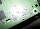
Note: All of the following photos are from a Tesla Model 3 FM/HD tuner part number 1079749-00-E. These are NOT photos of the Model X tuner with SXM.

#1 Top:

IMG_3997.JPG


#2 Bottom (with thermal compound residue (removed residue in close up later photos):

IMG_3996.JPG


#3 Bottom of PCB closer to antenna side:

IMG_4001.JPG


#4 Bottom of PCB below the above photo:

IMG_4003.JPG


#5 Bottom of PCB to the antenna side of the photo above:

IMG_4014.JPG


#6 Bottom PCB middle of board:

IMG_4008.JPG


#7 Bottom of PCB Ethernet/power side

IMG_4009.JPG


#8 Bottom of PCB slightly higher than above photo

IMG_4011.JPG


#9 Top of PCB

IMG_4013.JPG


I've hit the image limit for a post, but have a couple more shots on some a couple of the harder to read ICs. Let me know if you need me to post more.

If this problem annoys me enough perhaps I will wind up buying a module and bringing it into our lab for my guys to look at....they are much smarter than me.

I gotta say, I would love a more expert opinion than mine.
 

Attachments

  • IMG_4005.JPG
    IMG_4005.JPG
    376.1 KB · Views: 53
Here is my best guess with 10 minutes of searching before bed...don't hold me to it. I am not an engineer, I just tell them what to do and learn by osmosis.

Under the silver metal shield (a "can" for short) are matching networks for a few different frequencies (radio, satellite radio, etc). These networks them fan out to their respective signal paths - one for satellite radio (1.4-2.ghz range according to Google) and one for AM/FM (much lower, as we know - can't use the same path for both). The missing IC on that PCB is possibly a tuner/demod IC that operates in the satellite radio frequency range. I surmise this because it's on it's own path and the FM radio RFIC that is present on this PCB does not operate in the satellite radio range. The path to that IC is probably just terminated, while the FM/AM radio paths continue onto the SAF360x, which is an "all in one" radio IC. This IC handles tuning, demodulation, audio decoding, and has some rudimentary ADCs on board.

The SAA7706H is a DSP chip that has a lot more DSP resources than the radio IC does. I am guessing that if the satellite RFIC is present this would handle AD conversion for that (the SAF360 handles it for AM/FM), and also has an internal switch according to the datasheet. This is probably doing some final processing and controlling what gets sent through the ethernet interface.
 
  • Like
Reactions: sparkywatts
So I ordered a tuner and am going to try this as well in my 2019 model 3 SR plus. I was going to try this before, but didn't think the mcu would even see it. Here is the info so far that I have gathered on how the tuner and the mcu communicate. First they use automotive ethernet between the mcu and tuner, but it uses the broadReach single pair ethernet standard, so you can't just use any ethernet port to talk to it. I plan on ordering an adapter and sniffing the packets to see what it sends when requesting an fm channel vs sirius. I can say with certainty its not encrypted, as I came across a researcher that had actually sniffed the communication a bit between the tuner and other ethernet parts of the car fairly recently. The MCU has an ip of 192.168.90.100 and the tuner 192.168.90.30. When the tuner starts it requests an ip from the mcu and that's what it gets assigned. I suspect with a regular computer and an adapter you could pretend to be the mcu and get it to send you audio packets with the right message being sent. The researcher that sniffed this out used two FC602 USB Sticks and a raspberry pi acting as a forwarder gateway on 192.168.90.29. I suspect both audio sources are present on the tuner, and that the mcu only ever tries to decode one, or that the tuner doesn't understand the mcu audio source command as the firmware on the tuner maybe outdated for the mcu. It would be interesting to see if a tuner that's pulled from a newer model x or s and has up to date firmware would work differently. My plan is to sniff the commands and use a script to detect if a sirius tune message comes through, then rewrite the sirius audio packets to look like the fm ones that are coming through successfully. Then if an fm tune request comes through, stop rewriting the packets and simply pass through again. I won't know until I get into it some more what's truly happening. It could also be that fm is m4a audo codec and sirius is aac or some other codec and that the mcu can't decode. In that case the audio could be piped to a script and translated.