This is a bit incorrect. Page 20 of the installation guide tells you to put the giant loop of wire over the top if the wires come in the bottom, but it tells you to put the giant loop around the bottom if the wires come in the top.
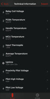
The temperature sensor is looking at the actual termination block, most likely in between L1 and L2. You can see it clearly as a small metal circle with a window in it on the back side of the 'body' of the HPWC. See the third picture(depicting the relative locations of the ground and temperature sensor) in
Gen3 HPWC disassembly, with overheating issues explained! and compare it to the picture just above.
Those loops are not critical to the operation. I'd wager they are intended to decrease any stresses that might occur due to wire heating/cooling since they give the wire somewhere to go. If you end up with not enough wire and go straight in, the termination block will get pushed and pulled, possibly wiggling the wires until they get loose and so on.
If you have to reroute to get more wire, I myself would leave the green wire where it is, and put smaller loops in L1/L2 at the bottom before they enter the terminal block rather than have them go straight in.