Welcome to Tesla Motors Club
Discuss Tesla's Model S, Model 3, Model X, Model Y, Cybertruck, Roadster and More.
Register

Gen 3 Wall Connector Wire and Conduit Question

This site may earn commission on affiliate links.
I have a MY LR 7 seater on order, Gen 3 WC being delivered this week. There are a few videos and several threads discussing the wiring used. The more i watch and read, the more confused I get. What I can gather so far is that Tesla recommends 6 gauge wire and some people are running 4 gauge romex bc 6 gauge romex is only rated to 55 amps. If I run 6 gauge romex inside flex conduit does this solve that issue?

50 feet of 6/3 armored conduit is $360 at home depot. Is there a solution that involves just buying the THHN 6 gauge by the foot and installing it inside of flex conduit? Does the conduit have to be armored or Non metallic?

Sorry for the ramble but i wish there was just a simple, "this is how you should do it" instructions this way I can rest assured that whomever I hire to do the install will be following what tesla recommends. TIA!
 
If you are installing the Gen3 Wall Connector you only need to run two wires, plus the ground. You won't need the neutral wire when you install the Wall Connector. This will save a little $, potentially easier to install.

There are variations in local electrical codes as compared with the national code. I.e., can I run this wire configuration in that gauge for a distance of XX feet; what about in conduit, in an enclosed space or inside a wall, inside a garage, down an outside wall, what if the temperature is over a certain amount? That is why you should leave it to the electrician.

Download, print the Gen 3 Wall Connector Installation Guide or send the installer the link. Everything that the installer would need to know about installing the Wall Connector can be found in the Installation Guide.

Get some quotes from recommended installers. Use only a licensed electrician. Have the necessary permits so that the work will be inspected, approved once completed. If there is ever an electrical fire your insurance company would check that the Wall Connector installation had been inspected, approved.
 
Last edited:
  • Like
Reactions: burn1010
... What I can gather so far is that Tesla recommends 6 gauge wire and some people are running 4 gauge romex bc 6 gauge romex is only rated to 55 amps. If I run 6 gauge romex inside flex conduit does this solve that issue?...
Definitely not. The issue is the 60C temperature rating, not the conduit. Putting it in conduit makes this issue worse, not better. It's simple, 6 gauge 90C wire in conduit (or MC wire), or 4 gauge 60C wire (4-2 or 4-3 NM-B) on a 60 amp breaker for a 48 amp continuous load.
 
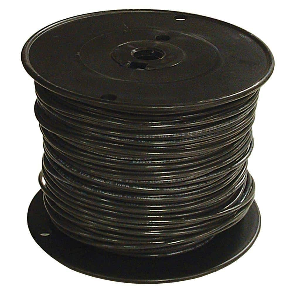
So 2 of these

Inside this

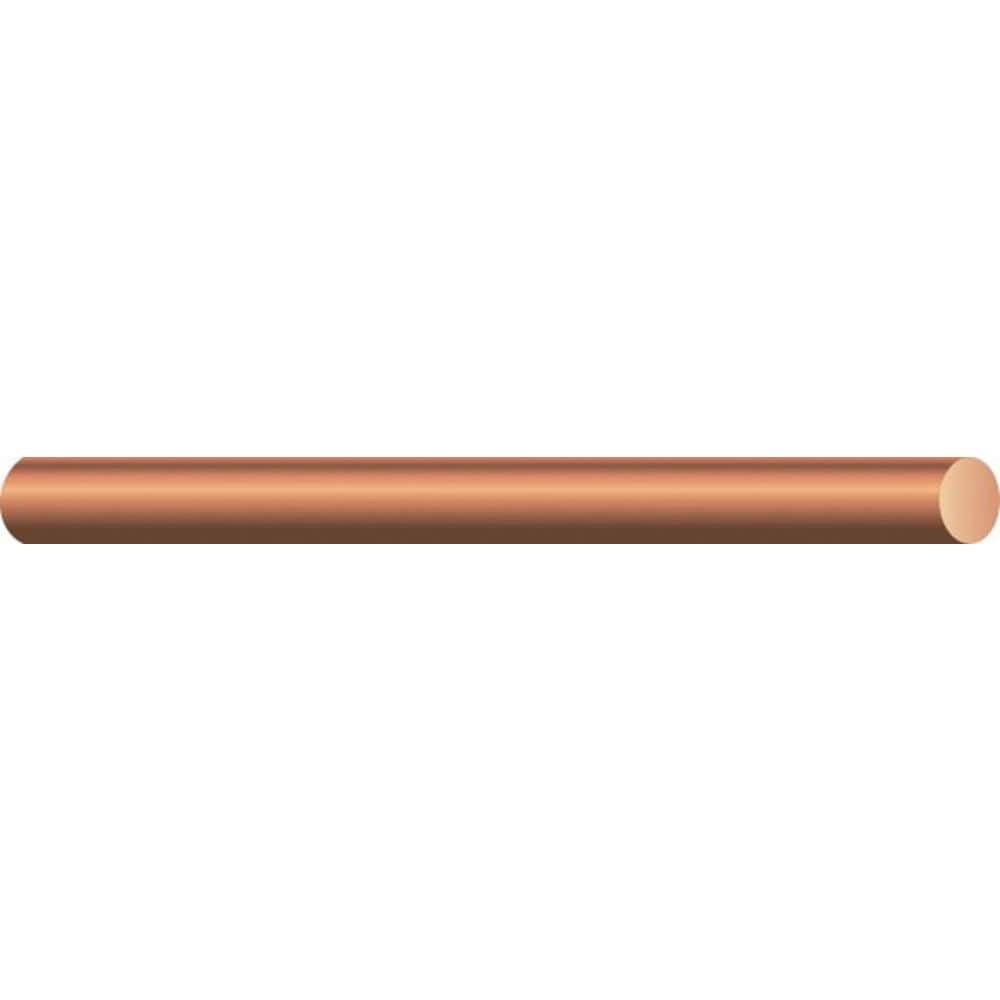
Using this to ground

does it matter what material the conduit is made of. I’m not sure if the conduit I linked is armored of just plastic

TIA!
 
Hey everyone. Does anybody have an opinion of my suggestion of materials in the above post? Much appreciated.
Looks right to me.
I would up the ground wire to a #8 instead of a #10, but that's my opinion.
I meant #6 wire
Why? I am pretty sure 10 gauge is the normal rated thickness for ground on 50 or 60A rated circuits. 8 would probably be extremely oversizing it, and 6 is just insane. The ground wire is never intended to carry any current, so it is always spec'ed to be much thinner than the current carrying conductors.
 
The benefit of upsizing to 4 gauge is slightly less voltage drop (power loss). Both the HPWC and 60A breaker can handle 4 gauge, so the larger wire doesn't cause any issue there. At 48 amps, it will create about 29 watts of heat in the 25' loop (50' of wire) with 4 gauge and 44 watts with 6 gauge.

I drop around 4 volts when charging at 48 amps. Thats means I'm wasting ~192 watts in heat. That's with ~65' of 2/0 Al wire feeding my garage panel (~48 watts at 48 amps), and ~35' of 4 gauge copper feeding my HPWC (~41 watts at 48 amps). Much of the noticeable heat is in the cord between the HPWC and the car, and in the breaker (high load breakers get warm).

I have an 18' HPWC cord, but could have used the short one. I suspect that's the majority of the remaining ~100 watts of loss in my circuit; it gets quite warm. If you want to conserve every watt, using the short cord HPWC is where I'd start.

For wire resistance, see: http://www.paigewire.com/wire_resistance-prop.aspx?AspxAutoDetectCookieSupport=1
 
Last edited:
You will want bigger conduit.
The Gen 3 wall connector has punchouts for 3/4" or 1" conduit. The Gen 1 wall connector only supports 1". If you are close to the fill capacity on the table, use the next size up. 1" is *far* easier to pull through than 3/4".
Consider running a pull line in case you later need a neutral wire.

Buy green or green-yellow insulated stranded 10AWG THHN wire, not bare solid wire. It's easier to pull, less likely to be damaged, and probably less expensive.

If you are buying wire by-the-foot or two 50 ft package, use one black and one red rather than both black. It doesn't matter here, but it can avoid ambiguity in other circumstances.
 
Last edited:
Your ground wire is actually called the "equipment grounding conductor", and Table NEC 250-122 dictates the size based on the upstream breaker. If you upsize the branch circuit for voltage drop, you also need to upsize the EGC.

If you are using metal conduit, you don't need an EGC, but it is recommended.
Thanks for the reply. So if I went with #4 wires are you saying I should revise the ground to perhaps #8?
 
The benefit of upsizing to 4 gauge is slightly less voltage drop (power loss). Both the HPWC and 60A breaker can handle 4 gauge, so the larger wire doesn't cause any issue there. At 48 amps, it will create about 29 watts of heat in the 25' loop (50' of wire) with 4 gauge and 44 watts with 6 gauge.

I drop around 4 volts when charging at 48 amps. Thats means I'm wasting ~192 watts in heat. That's with ~65' of 2/0 Al wire feeding my garage panel (~48 watts at 48 amps), and ~35' of 4 gauge copper feeding my HPWC (~41 watts at 48 amps). Much of the noticeable heat is in the cord between the HPWC and the car, and in the breaker (high load breakers get warm).

I have an 18' HPWC cord, but could have used the short one. I suspect that's the majority of the remaining ~100 watts of loss in my circuit; it gets quite warm. If you want to conserve every watt, using the short cord HPWC is where I'd start.

For wire resistance, see: http://www.paigewire.com/wire_resistance-prop.aspx?AspxAutoDetectCookieSupport=1
Thanks for the reply. Unfortunately I need the 18’ cord as I need flexibility depending on where I park the Tesla.

Sounds like I may consume less power and spend a little less money on my electric bill if I go with #4?
 
I'm probably going to the snarky penalty box again for this comment, but it seems you want to install this yourself without much knowledge, and you think that a flexible conduit with some wire in it is the easiest way to go. Trying to pull conductors through LFNC will be very difficult. Why not simply run EMT from end to end? It solves many problems like proper supporting, wire pulling, #90 degree bends and physical protection. Please reconsider your installation.

Also, If you are only 45 feet from the electrical panel then you do not have much voltage drop/I2R losses to worry about.
 
So if I went with #4 wires are you saying I should revise the ground to perhaps #8?
I looked up the table that was referenced there. The ground wire is based on the circuit value, not the thickness of the other wires. And that's why the table was given. Up to 60A circuits, a size 10 ground wire is appropriate. You don't need an #8. Once you go over 60A circuits and up to 100A, then that needs a #8.
Sounds like I may consume less power and spend a little less money on my electric bill if I go with #4?
lso, If you are only 45 feet from the electrical panel then you do not have much voltage drop/I2R losses to worry about.
Yeah, there's not much benefit there. Sure, it would save just a little bit in heat loss, but not much, since it's a short run, so marginal benefit. But the downsides are that it makes everything about the install more difficult and more expensive. The wire costs more. The labor costs more, trying to wrangle thicker stiffer wire, which takes more time. It needs thicker conduit. The pulling is more difficult, which adds to the labor time/cost. If you don't need that, to plan for a higher amp circuit in the future, it's usually not worth it.
 
  • Like
Reactions: MN-MS100D
Your ground wire is actually called the "equipment grounding conductor", and Table NEC 250-122 dictates the size based on the upstream breaker. If you upsize the branch circuit for voltage drop, you also need to upsize the EGC.

If you are using metal conduit, you don't need an EGC, but it is recommended.

Errmm, are you certain about? The grounding wire only need to be sized for the breaker, not the other conductors.
(I'm guessing that you actually mean "if you upsize the wire and breaker to more than 60 amps, you'll also need to increase the grounding conductor size". Edit: Or you might be remembering an interpretation of the 2011 and earlier code that has been clarified.)

The neutral wire ('grounded conductor') usually does need to be sized the same, but can be downsized in a few limited situations e.g. ranges and feeders. Except for feeders, it's best not to rely on those exceptions because your local rules or inspector might not agree.