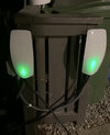
I have two Gen 3 wall connectors which I have setup using the load sharing feature. Both are on a single 60a breaker, so they are set to never pull more than 48a collectively.
This works great with my Teslas, but i may in the future want to charge a non tesla vehicle on these, and I'm just wondering if they will allow non Tesla's to charge while maintaining the Load Sharing limit?
I bought a Tesla to j1772 adapter for using with this, I do not yet have a non tesla to test, but i did put my J1772 adapter on the end to go back into my tesla, and it would NOT charge at all. I assume that could be because I adapted it too many times, but it was only for testing anyway.
Does anyone know if this is going to work like i think it will?