So, thinking further about the reason not to use a single pole breaker... power dissipation is current squared times resistance, so a current balanced double pole breaker with 0.02 ohms per contact will be dumping 11.5 watts per 24 amp leg, for a total of 23 watts. Putting 48 amps through a single 0.02 ohm contact would result in 46 watts of power dissipation, and that's a LOT of heat to get rid of.


Welcome to Tesla Motors Club
Discuss Tesla's Model S, Model 3, Model X, Model Y, Cybertruck, Roadster and More.
Register
Install the app
How to install the app on iOS
You can install our site as a web app on your iOS device by utilizing the Add to Home Screen feature in Safari. Please see this thread for more details on this.
Note: This feature may not be available in some browsers.
-
Want to remove ads? Register an account and login to see fewer ads, and become a Supporting Member to remove almost all ads.
You are using an out of date browser. It may not display this or other websites correctly.
You should upgrade or use an alternative browser.
You should upgrade or use an alternative browser.
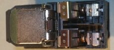
Gen3 HPWC disassembly, with overheating issues explained!
- Thread starter Sophias_dad
- Start date
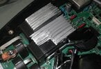
Pics of hacky heat sinks and removed-relay test harness.
In retrospect, the test harness was horrific overkill, and hard on the relay(soldering-wise). I later got perfectly fine results(for an 11 amp load) with just heavy alligator clips clamping tinned stranded to the contacts. The alligator clips themselves were the end of my meter probes, so I didn't have to concern myself with voltage loss across the alligator-clip-wires.
Stay tuned for the next post, just below, for the 'end of the story'!
Attachments
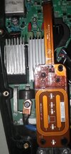
I managed to get the other relay off the board without too much trouble, and without breaking the relay or board, and it also showed very different contact resistances for the two poles.
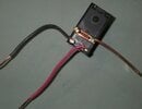
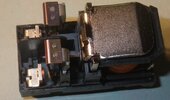
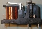
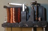
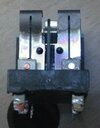
I decided after a while to carefully de-lid the relays and see what was going on. Here are some pictures of the innards of the relays. I had figured there may be a bad alignment or schmutz on the contacts, or whatever. Can't hurt to have a look!
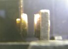
So of course I ran my 11amp tester over and over on the relays while they were open, and found that the voltage drop(and inferred resistance) was all over the place. Even bought some new test leads because I thought my old ones had become unreliable! I tweaked the alignment just a bit, but things stayed way more variable than I'd expect. Eventually, I took a better look at the spring-steel of the contacts and realized they were discolored not at the >contacts< but rather up at the top, where the spring steel is riveted to the other PCB connection! (see the last pictures), immediately that pointed me to the issue. The rivets hadn't been fully squished at the factory, and as I was tweaking the alignment or moving the relay in any way, the resistance at those rivets would change(note that the 'top' picture is actually AFTER I squished the rivets better). Notably, squishing the rivets completely closed the contacts even without applying power to the coil, so it was clear they were loose(r) before squishing.
As I was experimenting, I found:
Simply turning the coil off and on a few times(without load on the contacts, like a tesla would have) would make the resistance change a bit randomly.
As the contacts were warming up, they would decrease their resistance a bit, to a point.
The alignment and angle of the contacts was not anywhere near as important as I expected. The 2 milliohm resistance contact is visibly cockeyed(not flat-to-flat), but I didn't want to screw with it.
After squishing and readjusting the contacts, I rechecked resistances and found that one relay had a pretty closely matched 6 milliohm resistance for each contact, and the other had 2 milliohm and 6 milliohm for its two contact resistances. Doing the math, that got me to about 6 watts total dissipation for the first relay, and 4 watts for the other relay(both at 48 amps, apportioned appropriately for the contact resistances).
I was very satisfied with these results, of course, I re-lidded both relays with high-temp epoxy, reattached them to the board(adding a bit less than 1/16th inch spacing off the board for better airflow, and nipping off the excess wire of the optical temperature sensor that extended through the board). I was careful to put the 'better' of the two relays over the temperature sensor, but I really don't think it matters.
I reassembled the entire thing(no hacky heatsinks!), and she lit right up and gave Stacy's Mom some electrons! Sadly, I had Stacy's Mom to only accept 24 amps from the last time I tried this charger, but figured that out after a few hours of grumbling over what could be wrong, and taking it back apart. Finally set Stacy's Mom to 48 amps, and it ran right up there. Since the covers were off now, I could feel that the relays were only slightly warmer than ambient temperature(60f) after a half hour of 48 amps. Additionally, the voltage losses from in-to-out on each leg were 0.08 volts, much better than the prior 0.21 and 0.285, respectively.
I've now put all the covers back on and fully expect my next infinite hour charge session to go just fine!
I decided after a while to carefully de-lid the relays and see what was going on. Here are some pictures of the innards of the relays. I had figured there may be a bad alignment or schmutz on the contacts, or whatever. Can't hurt to have a look!
So of course I ran my 11amp tester over and over on the relays while they were open, and found that the voltage drop(and inferred resistance) was all over the place. Even bought some new test leads because I thought my old ones had become unreliable! I tweaked the alignment just a bit, but things stayed way more variable than I'd expect. Eventually, I took a better look at the spring-steel of the contacts and realized they were discolored not at the >contacts< but rather up at the top, where the spring steel is riveted to the other PCB connection! (see the last pictures), immediately that pointed me to the issue. The rivets hadn't been fully squished at the factory, and as I was tweaking the alignment or moving the relay in any way, the resistance at those rivets would change(note that the 'top' picture is actually AFTER I squished the rivets better). Notably, squishing the rivets completely closed the contacts even without applying power to the coil, so it was clear they were loose(r) before squishing.
As I was experimenting, I found:
Simply turning the coil off and on a few times(without load on the contacts, like a tesla would have) would make the resistance change a bit randomly.
As the contacts were warming up, they would decrease their resistance a bit, to a point.
The alignment and angle of the contacts was not anywhere near as important as I expected. The 2 milliohm resistance contact is visibly cockeyed(not flat-to-flat), but I didn't want to screw with it.
After squishing and readjusting the contacts, I rechecked resistances and found that one relay had a pretty closely matched 6 milliohm resistance for each contact, and the other had 2 milliohm and 6 milliohm for its two contact resistances. Doing the math, that got me to about 6 watts total dissipation for the first relay, and 4 watts for the other relay(both at 48 amps, apportioned appropriately for the contact resistances).
I was very satisfied with these results, of course, I re-lidded both relays with high-temp epoxy, reattached them to the board(adding a bit less than 1/16th inch spacing off the board for better airflow, and nipping off the excess wire of the optical temperature sensor that extended through the board). I was careful to put the 'better' of the two relays over the temperature sensor, but I really don't think it matters.
I reassembled the entire thing(no hacky heatsinks!), and she lit right up and gave Stacy's Mom some electrons! Sadly, I had Stacy's Mom to only accept 24 amps from the last time I tried this charger, but figured that out after a few hours of grumbling over what could be wrong, and taking it back apart. Finally set Stacy's Mom to 48 amps, and it ran right up there. Since the covers were off now, I could feel that the relays were only slightly warmer than ambient temperature(60f) after a half hour of 48 amps. Additionally, the voltage losses from in-to-out on each leg were 0.08 volts, much better than the prior 0.21 and 0.285, respectively.
I've now put all the covers back on and fully expect my next infinite hour charge session to go just fine!
Attachments
Last edited:
They don't.So…. How do they claim a software update will fix a bad relay setup? Ignore the heat buildup?
Around version 1.4.4, they changed the overheat behavior to gently roll back the current rather than either cutting it to 24 or 0 amps.
In my case, it would roll back to 40 amps or so. I don't know that it would be long-term-survivable for the charger though, the board was getting VERY hot. Since I now know that all that heat was focused on one small connection in each of the relays, I'd be concerned of a literal meltdown.
I'd DEFINTELY suggest anyone that has an overheating charger even once in a while should get Tesla to warranty-replace it. (If you happen to have a used-but-prone-to-overheating Gen3, let me know and I might give you some dough for it!)
I'd also be VERY wary of buying used Gen3's (maybe only the -F revision, I don't know for sure) on the open market right now unless they have been stated as running successfully at full power for hours. at least if you plan to use them for more than 32 amps.
Last edited:
Final message on this...just got done with a 3.5 hour 48 amp charge session with the renewed Gen3 in my 60f garage, and the results are as good as I could hope for.
The glass faceplate got to 95f.
Just above the sticker on the left side of the charger where the relays live, if I searched REALLY hard, I could find 116F. More general temps were around 100-105f.
Moments after charge stopped(and the charger removed from its baseplate in seconds because I've not been using means other than screws to hold it up), the input conductor lugs were at 116f. This sort of surprised me because I'm using 6AWG in NMB to feed it(technically not allowed to move 48 amps except during science experiments!). Might also be notable that there's only a 50 amp breaker on the subpanel.
Still seconds after charge stopped, the area around the temperature sensor directly under the relays were 136F in one small spot, with a more general ~110F in the area.
Near the end of the charging session but still during charging at 48 amps, I checked the NMB cable temperature where it exited my subpanel and it was only 88F, not remotely near the 140F(60C) limit. I sort of already knew this, but the NEC rules appear to be extremely conservative. They have to make rules that apply both to my 65F all-the-time basement with one NMB cable in free air for 95% of its length(stapled to overhead floor joists every 3 feet or so) and to several NMB cables squeezed through a marginally too-small hole in an attic in Texas during summertime(~130f with the power turned off) and so on. They probably also add even more safety margin in case someone stretches the rules a bit. I know there are ambient-temperature adjustment tables, but I imagine they aren't consulted anywhere near often enough.
You're right on both counts. Sounds like the RS-485 will remain useless forever. Unless they just had to put it on to fill the hole in the plastic, I'm surprised they even put the RS-485 connector on the board.
The RFID might become interesting. I could see Tesla making some sort of registered-users list where you wave your car's keycard at the faceplate before it enables power. If my plate weren't so full it might be a fun exercise to try and implement.
The RFID might become interesting. I could see Tesla making some sort of registered-users list where you wave your car's keycard at the faceplate before it enables power. If my plate weren't so full it might be a fun exercise to try and implement.
@Sophias_dad Wow, that was a very educational read.
What revision number is your Gen 3 charger? Would you happen to know what the currently shipping rev number is?
Really appreciate the work you've put into this. Makes me wish I would've bought a 2nd Gen2 Wall Connector when I bought my car. : /
What revision number is your Gen 3 charger? Would you happen to know what the currently shipping rev number is?
Really appreciate the work you've put into this. Makes me wish I would've bought a 2nd Gen2 Wall Connector when I bought my car. : /
TBrownTX
Active Member
@Sophias_dad Wow, that was a very educational read.
What revision number is your Gen 3 charger? Would you happen to know what the currently shipping rev number is?
Really appreciate the work you've put into this. Makes me wish I would've bought a 2nd Gen2 Wall Connector when I bought my car. : /
Pretty sure it’s the -F revision. I purchased one in Late December, so they have been shipping the -F revision at least since then.
Tim
Mine is definitely -F, as shown on my first post and in the pictures. I believe they switched to -G, perhaps when they got a known-good batch of relays!
Apparently some -F's are just fine, too.
Apparently some -F's are just fine, too.
Last edited:
TBrownTX
Active Member
Mine is definitely -F, as shown on my first post and in the pictures. I believe they switched to -G, perhaps when they got a good batch of relays!
Apparently some -F's are just fine, too.
My mistake, I just double checked, mine is actually a -G revision, purchased in late December of last year.
Tim
Yippydog
Member
just to share my experience:
I was getting the three red blinks a month ago. Went through all the the 2nd guessing that my installation was clean. Right conductors, breakers, torque on the terminal block; the whole nine yards. Then called Tesla support. They basically said we need to replace your wall on connector as it’s model number ends in “F”. Translation: We have fixed the design flaw. The new unit that we are sending you(with model number ending in G) fixes the overheat issue. Sure enough it does as my new unit does not even get warm after 2 hours of 11KW or 48A charge current. I do appreciate the tear down and wall of text as well as all of the comments. If you gen3 wall connector model number ends in F, call Tesla and they’ll ship you a new one. Along with 18’ cable as well even if you have the 8’ one!
I was getting the three red blinks a month ago. Went through all the the 2nd guessing that my installation was clean. Right conductors, breakers, torque on the terminal block; the whole nine yards. Then called Tesla support. They basically said we need to replace your wall on connector as it’s model number ends in “F”. Translation: We have fixed the design flaw. The new unit that we are sending you(with model number ending in G) fixes the overheat issue. Sure enough it does as my new unit does not even get warm after 2 hours of 11KW or 48A charge current. I do appreciate the tear down and wall of text as well as all of the comments. If you gen3 wall connector model number ends in F, call Tesla and they’ll ship you a new one. Along with 18’ cable as well even if you have the 8’ one!
Donaldinc
Member
Did you need to install the entire base and reconnect the wires from the replacement or just the cover?just to share my experience:
I was getting the three red blinks a month ago. Went through all the the 2nd guessing that my installation was clean. Right conductors, breakers, torque on the terminal block; the whole nine yards. Then called Tesla support. They basically said we need to replace your wall on connector as it’s model number ends in “F”. Translation: We have fixed the design flaw. The new unit that we are sending you(with model number ending in G) fixes the overheat issue. Sure enough it does as my new unit does not even get warm after 2 hours of 11KW or 48A charge current. I do appreciate the tear down and wall of text as well as all of the comments. If you gen3 wall connector model number ends in F, call Tesla and they’ll ship you a new one. Along with 18’ cable as well even if you have the 8’ one!
Did you need to install the entire base and reconnect the wires from the replacement or just the cover?
Only the cover, even if they send you another base. The base is completely dumb(no sensors of any sort).
Donaldinc
Member
Super helpful, thank you! Firmware did not work for me, so I'll have to contact them in hopes of getting a replacement.Only the cover, even if they send you another base. The base is completely dumb(no sensors of any sort).
Very well done. Should be a sticky if not already. For the sake of safety, Tesla should recall all the F models and have them replaced.
Ruffles
Member
FYI - I bought one from Tesla last week and what I got has this part number: 1457768-01-G. So far, no issues with over heating.
Soo... I picked up another Gen3 on ebay that "couldn't be tested", but lit up okay. To translate: "it didn't work at all other than the pretty green light, and we wanted some cash out of it". Should have known ")
I plugged it in and it clicked the contactors on, but it sounded a little funny. It gave 0 volts to my 3, great sadness ensued. Of course I ripped the cover right off and found one of the relays wasn't actually relaying anything at all. Removing the board from the body, it became very clear why. One relay had gotten so hot it melted the relay guts until the movable contacts pulled away from the stationary contacts! Those two dots on the contacts are plastic thats intended to push the relay contacts closed, and not intended to actually melt to the contacts. They did melt, the contacts retracted, power stopped flowing, and the Gen3 got put on ebay.
Of course, I'm not one to let something like that get the better of me, so I freed the contact from the plastic, readjusted the contacts repeatedly until I got decent resistance, and put it all back together.
After the fix, one relay showed 0.115v loss and the other had only 0.095V loss.
Stacy's Mom is currently charging at 48amps/227V, 41 mph(we have generally low voltage, even unloaded). The relays are warm, maybe a bit warmer than I'd like, but I don't think they'll cause a throttling.
The strange thing is that the unit as delivered was only set to 32 amps. This means that the connections had to be so very bad AND consistent that they melted both poles at the same rate, and with each pole only taking around 16 amps. I'd think this would have made the HPWC fail during the warranty period, but whatever.
Attachments
TomServo
Active Member
My G version should arrive any day now (Tesla shipping is abysmal) and would it be safe to say they fixed the issues seen with the F models?
Similar threads
- Replies
- 5
- Views
- 1K
- Replies
- 2
- Views
- 446
- Replies
- 17
- Views
- 2K
- Replies
- 8
- Views
- 1K
- Replies
- 19
- Views
- 1K