Welcome to Tesla Motors Club
Discuss Tesla's Model S, Model 3, Model X, Model Y, Cybertruck, Roadster and More.
Register

Help: VIN 729 Roadster not starting, VMD-VDS communication fault

This site may earn commission on affiliate links.
Recently I’ve noticed that the battery is getting out of balance, with a voltage difference as big as 0.3V, and the BMS does not seem to be able to balance it automatically. I do not have a home charging facility, instead I mainly use public charger with an adapter. I know that’s not the best way to charge a Roadster and I did try to find always-on chargers for a few times to hope the car can balance the cells but it didn’t seem to work, maybe I should’ve have let it charge for longer. However, instead of doing that, I decided to pull the BMB boards and balance it myself, which turned out to be a stupid decision…

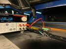
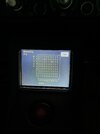
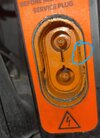
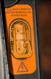
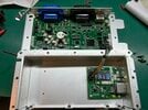
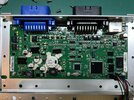
So I inhibited the APS, and the first problem happens when I pulled the service plug, the handle of the plug broke… Since I’ve already pulled it out I decided to continue any way… I then pulled two BMB boards out and find the one with minimum voltage (3.68V), and put the other one back in. The other bricks are about 3.99V. I then inserted a “trickle charging” BMB board (thanks Nick for designing those boards) to the slot that has the lowest voltage brick, and connected to a power supply that can do constant voltage and constant current charging. I originally set the charging current at 0.1 A for a few hours and realised it is gonna take forever to charge it from 3.68V to 3.99V. So I increased the current to 0.4A, let it charge for about 2 days and only got to 3.72V. I lost my patience and also worried that other cells may also go out-of-balance so I stopped it and put the BMB board back in.

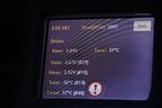
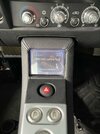
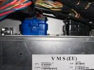
Since the service plug handle is broke I then glued a customised handle and plugged back in. After about 30 seconds, the VDS screen turned on with a “VMS-VDS communication fault, ID: 1900” message, and everything seemed reset, time is out of sync. The VDS also asking for a new Pin for the vehicle but after entering the Pin there’s no response. It couldn’t go to diagnostic mode either. Everything else e.g. doors, keys, hazard lights does not work either. Car couldn’t start. I then realised that OVMS was left plugged in during this time and that might have drained the 12 V battery. So I measured the voltage across the 12V battery, it was 13.2V. However when I disconnect the cable that connected to the 12V battery, the voltage of the battery was only 8.3V. So it seems that the battery is dead, but the main ESS is able to provide 13V to supply the vehicle… I got confused, the problem seems like the VMS is not started or faulty but the VDS is on and working. I thought maybe the BMB boards or the ESS disconnect plug were not inserted properly but how could the ESS still supply 13V if that is the case? I did try pull out and put back in the ESS disconnect a few times but is the same problem. I also tried to supply the 12V a power supply and noticed a 50W power draw and slowly settled to 37W, the two amber lights in the front of the car turned on and I guess that's drawing the power. Even with the 12V power supply the VDS screen does not turn on, it only turns on when the ESS disconnect is plugged in, and VDS stills shows the same VMS-VDS fault message. I also tried to flap the charging port door many times and that did not help.


I then thought could it be a fuse blown due to the high current surge to charge the low-voltage 12V battery when I put the ESS disconnect back in? If that’s the case where should I check and replace the fuse?

Any other ideas about what is going on?

Thanks for your time!


Attachments

  • BMB-charging.jpg
    BMB-charging.jpg
    408.4 KB · Views: 249
  • ESS-balance.jpg
    ESS-balance.jpg
    709.9 KB · Views: 176
  • ESS-balance2.jpg
    ESS-balance2.jpg
    250.7 KB · Views: 179
  • VMS-VDS-comms-fault.jpg
    VMS-VDS-comms-fault.jpg
    500.5 KB · Views: 186
You have a bad cell(s) in brick #29. You need to remove the sheet from the ESS and cut the connection to the bad cell(s).

The ESS disconnect has a pin on the handle that activates a microswitch when in the locked position. Did you take that into account when you repaired the disconnect? Nothing works without it.

The car is trying to balance the pack, but the drain from brick #29 is faster than the car can balance (one of the two zeros in the balance screen is #29).

There is nothing you can do until you stop the bad cell(s) from draining brick #29 and possibly #66(the other zero) as well. The longer you wait the closer you get to ruining the other cells in the low brick.

Many a Roadster has been bricked from just one bad cell-don't let yours become the latest.
Thanks for your reply! You're right, the service disconnect handle is indeed broken and that is one of the reasons the car does not start. However, does the VMS boot in this case? I'd thought the VMS would still power up to tell me that the service plug was not inserted properly. I do also worry that the APS is down as x.l.r.8 suggested.

Can I ask if there's any other way of purchasing the service disconnect other than Tesla SC? The car is now in China and the SC here does not have this part. I've contacted SC HK and still waiting for a response. I also tried to find the Smart EV plug but can't find where to purchase it...

While I am sorting out the service plug, I would like to power the 12V electronics of the vehicle with an external power supply. I've read from some posts that this is possible but not 100% sure which two pins to connect to. I took the right rear wheel out and saw infinite connectors there... I'd be really appreciative if anyone could let me know which connectors I can supply the 12V APS. Thanks!
 
For the APS power - in front of the right rear wheel there is a small black box with a terminal block inside. Large wire with red tape connected to it. Next to the coolant pump(s). That is the positive. Ground is just to the chassis.
Dear ML Auto, huge thanks for your help! I'll give it a try later today. I love this community!
 
So I supplied the vehicle APS with an external 12V power supply. Some part of the car starts running, the cooling pumps are pumping, the VDS screen lit up, all the shift buttons illuminate red. However, the VMS did not seem booted as the VDS still shows the same VMS-VDS comms fault, and could not enter diagnostic mode. The doors not working, the dash does not work even with the key on. It seems that the VMS is dead... Does anyone have any experience in debugging the VMS? The location of the VMS seems quite tricky to reach. Does anyone know how the VMS is powered? Is there any easy way to check its power supply? Is there a fuse for the VMS? Sorry for so many questions...

Thanks for your time.
There are two 12v power sources, but since you likely dont have APS enabled due to service disconnect switch (microswitch) is open... get new service disconnect first then try again.
 
So I finally received a brand new service plug from Tesla SC.

However when I inserted it the vehicle still shows the same problem - VDS screen showing a "VMS-VDS comms fault", but nothing else works. OVMS is on but not providing any information about the car except an 11.8V voltage (from the CAN bus?). Everything else is not working, even with the key on. The cooling pump is not working, and I guess that's expected as I inhibited the APS before pulling the service plug, I also measured the APS power via the connectors ML Auto suggested, and it's only 0.2V.

I did not connect the 12V battery before inserting the service plug, however the 12V battery connectors are showing a voltage around 12V. I did also try to connect a good 12V battery before inserting the service plug and still the same.

Also tried to supply an external APS power with a 12V battery, and it's showing the same thing as before, the cooling pumps are pumping, the VDS screen lit up, all the shift buttons illuminate red. But VDS still showing the same VMS-VDS comms fault message.

I have been communicating with Mark regarding this issue and he gave me some useful suggestions (really appreciated!) e.g. a hard reset on the VMS. So I unplugged the black and blue VMS connectors, waited for 30 seconds, and put them back in. No luck...

I also checked all the fuses on the fuse panel, all looking fine.

I am going to double-check if the BMB boards are inserted properly, but since the ESS is providing power to VDS and the 12V battery I believe the VMS should be powered as well?

So I now assume the problem is around the VMS, either the VMS power supply or the VMS itself. I've heard that VMS is powered from various sources e.g. the APS and 12V battery, and I tried to provide power to both of them but VMS still doesn't seem to work. So most likely the VMS is dead?


Please let me know if there's anything else I could try to debug this vehicle, many thanks!
Forgot to attach some photos...

I also noticed that there's only one metal spring contact inside the ESS service socket (see attached photo), is this normal?
 

Attachments

  • eccdea38d2de4d5acc9f9e8698285f7.jpg
    eccdea38d2de4d5acc9f9e8698285f7.jpg
    283.1 KB · Views: 144
  • c2435a5f0af734dcf3d690215631952.jpg
    c2435a5f0af734dcf3d690215631952.jpg
    169.8 KB · Views: 143
  • 4dfce9fcb244a8a2c5e1ea4c1bc59a5.jpg
    4dfce9fcb244a8a2c5e1ea4c1bc59a5.jpg
    353.2 KB · Views: 129
  • 42f04441eeac7d4eb2a99bf0f77bc68.jpg
    42f04441eeac7d4eb2a99bf0f77bc68.jpg
    200.6 KB · Views: 147
Forgot to attach some photos...

I also noticed that there's only one metal spring contact inside the ESS service socket (see attached photo), is this normal?
Yes there is only 1 microswitch. when you put down the handle you should hear a slight click of the microswitch. Also when you first plug in the service disconnect do you hear a slight pop sound? It's the spark created from of the battery charging up the caps in the APS.
Also you can open the VMS there are at least 2 green LEDS, the one labeled DS1 is the one your intersted in, and it should come on and blink if I remember right.
If you still get nothing, guessing an fuse blew or APS is not turning on for x reason (internal blown fuse, or maybe BMS telling APS to turn off (sheet alarm)).
 
This is very strange-I just had the exact problem with one of my cars yesterday. Completely dead, doors wont open. It was fully charged a week ago. After getting into the car I got the "no responce from PIN" from the VDS. Powered up the APS-still nothing. Looked like a dead VMS. Checked all the voltages to it and all was OK. Swaped in another VMS from another car and it booted up with all the expected module mismatch codes-so dead VMS. I Opened up the VMS and found burned wires on the antenna leads. Those leads connect to a separate communications board inside the VMS. I unplugged the board and put the VMS back in the car. To my surprise, everyting booted up and worked. Strange there would be enough current to the antenna to actually melt the wires. I checked the antenna and the two leads were not shorted with 0 ohms resistance. I'm not sure how an open antenna lead can burn itself up. Intermittent short I guess-but the car hadn't moved (inside, so no lightning either). It appears some short in the communications board was keeping the VMS from resetting.

The VMS is just held in place with two 8mm nuts on one side, and slides into brackets on the other. Takes just a few minutes to get out. The hardest part is getting your hands under the dash. Just a dozen or so tiny screws to get it apart. Take it apart and see what happens.
 
  • Informative
Reactions: eHorses
Were the wires just brittle over time or actually burnt brittle?
Interesting none the less. It's not unheard of having older 2G baseband modem to go bad (i.e. has it's own eeprom/microcontroller/PMIC on it).
The antenna lead actually melted through, and the inside of the unit had smoke residue. It was burnt all the way to the exterior plug, so it wasn't an internal short. If I ever a reason to take the dash apart, I'll remove the antenna and see if the wire shorted against something.
 
Yes there is only 1 microswitch. when you put down the handle you should hear a slight click of the microswitch. Also when you first plug in the service disconnect do you hear a slight pop sound? It's the spark created from of the battery charging up the caps in the APS.
Also you can open the VMS there are at least 2 green LEDS, the one labeled DS1 is the one your intersted in, and it should come on and blink if I remember right.
If you still get nothing, guessing an fuse blew or APS is not turning on for x reason (internal blown fuse, or maybe BMS telling APS to turn off (sheet alarm)).
Thanks for your help. Yes I did hear the pop sound when inserting the service plug, and the slight click sound of the microswitch, so that all seem fine.

I managed to drop The VMS (thanks to ML Auto for the instructions), and opened up to check the LEDs. I disconnected the 2G modem as ML Auto did for easy access. The DS1 remains on regardless, DS2 blinks very slowly when service plug pulled, and faster (~1 Hz) after inserting the service plug. However regardless of the status the VDS screen does not seem to be able to talk to the VMS, and OVMS does not report anything from VMS either, except a 11.8V from can bus.

I’ve attached the photos of the VMS, I cannot see any obvious damage by the look of it.

Is there anything else I can try except a firmware reflash?

Thanks!
 

Attachments

  • 31B4C4A4-8FA5-4615-92AF-F1A5DD174FB6.jpeg
    31B4C4A4-8FA5-4615-92AF-F1A5DD174FB6.jpeg
    506.2 KB · Views: 136
  • 9099ACA0-25A5-4CFA-A176-8940541BADAF.jpeg
    9099ACA0-25A5-4CFA-A176-8940541BADAF.jpeg
    651.1 KB · Views: 135
Having worked on this, I feel the need to warn users about powering off the VMS without proper shutdown.

There appears to be a bug in Tesla VMS firmware (I suspect in the bootloader) where if the VMS is improperly shutdown (power pulled when running, or some other interruption during boot) the file system can become corrupted. The symptom for this is that either the linux.bin (Linux kernel) or vms.initrd (initial ram disk) files are missing on /flash disk. In such cases, the VMS will be reachable on the CAN4 diagnostics, but none of the other VMS traffic will respond, the VDS will report a communication prompt and be useless. VMSIO is unaffected. Reportedly this has already happened in several cases.

I don't think this is a normal filesystem corruption. The files are not damaged, they are simply removed. And these files should not be written in normal circumstances so should not be actively being changed during the shutdown.

The fix is not trivial, and requires proprietary engineering tools to accomplish. An equivalent replacement linux.bin or vms.initrd image needs to be uploaded to the VMS and put back on /flash with the correct name. Making a backup of linux.bin and vms.initrd on the same flash is useful, as it will simplify recovery should the problem happen again in future.

The correct way to power off the VMS imho is to a) inhibit APS, b) stop the VMS application, c) pull the service disconnect (optional?), and d) cleanly and smoothly powering down the VMS. Similarly, when powering on, the power should be applied smoothly. I would plug in J3 before J2. As the VMS is powered by both APS permanent power as well as BPS (little 12v) in 2.x cars, care should be taken to ensure that the BPS is good before messing with service disconnect.