Welcome to Tesla Motors Club
Discuss Tesla's Model S, Model 3, Model X, Model Y, Cybertruck, Roadster and More.
Register

Home charging options with full panel

This site may earn commission on affiliate links.
I’m hoping someone can help me make sense of my charging options at home and hopefully find a way to charge faster than the 3 miles from a 5-15 outlet without having to spend thousands on rewiring or installation costs.

Right now I have solar and looking at two options:
  • Converting 5-20 outlet to 6-20 outlet
  • Installing wall charger
My preference is to go with #1 since it should hopefully be the cheapest and I don’t need the fastest charge because I don’t drive a lot of miles every day. I have a 200 amp electric panel, but it only holds 20 breakers and it’s completely full.

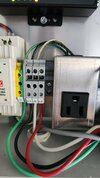
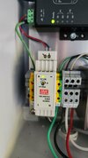
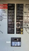
The 5-20 outlet has its own breaker and is the only receptacle on the line with a 15 amp breaker. The breaker marked “Solar Monitor” is a double pole 20 amp breaker, but it connects to a 120v single outlet which splits to the monitoring device.

Is there a way to easy change out the 5-20 to a 6-20 given this configuration? If not, would it be possible to change the receptacle on the “Solar Monitor” line to a 6-20 instead?
 

Attachments

  • monitor.jpg
    monitor.jpg
    278.2 KB · Views: 195
  • monitor2.jpg
    monitor2.jpg
    216.4 KB · Views: 126
  • panel.jpg
    panel.jpg
    373.5 KB · Views: 124
Below the quad at the bottom right are two 15 AMP breakers. You could put another quad there, but…

Those two 15 AMP breakers look like GFIC breakers, so assuming they go to outlets you will need to change those outlets to GFCI so you don’t need those GFCI breakers.

You will have to install a Wall Connector on the new 240V circuit since that is the only way to avoid needing a GFCI breaker for the new 240V circuit. All “outlets” for an EV will require a GFCI breaker.

OR if that Solar Monitor breaker is only a single 120V circuit you can put the quad there. However, it seems really odd to use a double breaker for a single 120V outlet, so check very carefully.

But given as full as the box is, I think it is time to add a sub-panel.
 
Thanks for the info on it. On the Solar Monitor breaker, it is connected to the single outlet in the picture. At the bottom, the wires leading in look like 240v then at the top it is only 120v to the outlet. It connects to that rail device but that's why I'm not sure if I can swap it with a 6-20?
 
Thanks for the info on it. On the Solar Monitor breaker, it is connected to the single outlet in the picture. At the bottom, the wires leading in look like 240v then at the top it is only 120v to the outlet. It connects to that rail device but that's why I'm not sure if I can swap it with a 6-20?
Odd, but if the extra wire is in fact not connected to the outlet you should be able to replace it with a 6-20 outlet, but you will need to replace the double 20-amp breaker with a GFCI double 20-amp breaker. Also confirm the 120V line terminates at the existing outlet.
 
  • Like
Reactions: Joe Schmoe88
but it only holds 20 breakers and it’s completely full.
That panel isn't 'really' full, though. There are 20, 40, and 50 amp duplex breakers in there, and I'd suspect you can get a tandem-duplex that would cover at least the 20/40 pairs, leaving you with space for a GFCI of your choosing, or you could do a 20/30 tandem-duplex and feed the 30 into an HPWC.


You have a 20/40 panel. Which means it’s got 20 full spaces and 40 mini spaces. This breaker will solve your problems.

So if I understand this correctly, I can replace the 50 amp breaker in the lower left of my panel with this? I could then keep the 50 amp circuit which is already on that breaker and move the 5-20 circuit to this one, replace the outlet with the 6-20 and be good to go?

If the wire gauge is thick enough could I potentially change the 5-20 circuit to something like a 6-50 since that breaker is 50/50A?
You can't move a 5-20 or 6-20 circuit to the 50/50 breaker, you'd want a 50/20 breaker(which they probably make, look for BQC250220 or BQC220250). It'd probably be easier to combine the 40 and 50 amp circuits with a BQ240250. (note that I haven't looked up the difference between BQC and BQ breakers, but they both say they fit in BR loadcenters.

This would leave you with a very convenient two-bay spot in the lower left that you could fill with a GFCI or not-GFCI breaker, depending on whether you are putting an outlet on the other end or not.
 
So if I understand this correctly, I can replace the 50 amp breaker in the lower left of my panel with this? I could then keep the 50 amp circuit which is already on that breaker and move the 5-20 circuit to this one, replace the outlet with the 6-20 and be good to go?

If the wire gauge is thick enough could I potentially change the 5-20 circuit to something like a 6-50 since that breaker is 50/50A?

I didn’t note that you already had the circuit ran. No the 5-20 circuit won’t have the wire size necessary to hook up to a 50 amp breaker. You’d need to refereed the breaker. Now that I think about, that would only work for the HPWC since if you need an outlet like a 6-50 it has to be GFCI protected. I guess you could run the wire to a hot tub disconnect and then to the outlet.

I believe that the C in BQC stands for circuit limiting @Sophias_dad

Most mini breakers have a little metal tab that prevents lthem being installed in a space not suitable for mini breakers. But they also sell breakers without the metal tab, because “some old panels don’t have the notch ;)”)
 
Last edited:
Sorry, I didn't elaborate on what I would switch in the scenarios which could cause some confusion that I see now. Given the quadplex breaker, I would most likely replace the 50 amp breaker. From there would I be able to do either of these changes:
  • Install 20/50 amp breaker (like BQC220250) and switch the receptacle to 6-20 since the wire gauge should be sufficient.
  • Install 40/50 amp breaker (like BQC240250), run new wire to receptacle since it probably isn't right gauge, and most likely install the wall charger.
I really appreciate all the help! I never would've known about that breaker without the recommendation.

Just for completeness, you really aren't supposed to wire a receptacle(that'll power an EV) to a BQC220250, since its not GFCI protected.
 
I believe the wall charger has integrated GFCI so this would only be an issue if I went the 6-20 route, correct?
The Wall Connector and the Mobile Connector each have GFCI protection designed to protect the user when plugging the Tesla charging connector into the Tesla vehicle's charging port. (All electric vehicle service equipment have this GFCI protection.) What has changed is that starting with the 2017 revision of the national electrical code is that any new receptacle installed for use for EV charging (i.e NEMA 14-50, 6-50, 14-30, 6-20, 5-20 and 5-15) must be protected by a separate GFCI for the receptacle. This GFCI protects the user when plugging and unplugging the equipment from the receptacle.

Sometimes there is a GFCI receptacle available that you can install such as the 5-15 or 5-20. Other receptacles must be protected by a GFCI at the circuit breaker. This is the case with the NEMA 14-50 as there is no 14-50 receptacle with GFCI built into the receptacle. Again, this only applies to new circuits for EV charging that terminate at a receptacle, existing receptacles are grandfathered. Hard wired circuits do not require a GFCI circuit breaker.
 
I believe the wall charger has integrated GFCI so this would only be an issue if I went the 6-20 route, correct?
You had specifically written:
"Install 20/50 amp breaker (like BQC220250) and switch the receptacle to 6-20 since the wire gauge should be sufficient."

And that would require a GFCI breaker, which cannot be achieved with a tandem duplex breaker like the BQC220250. All the 240 volt GFCI breakers I've seen take two full spaces of the panel for the one 240V circuit.

And yes, you wouldn't need, and shouldn't have, a GFCI breaker for the wall connector.

TBH, the math has been done several times, and you don't save very much by going the receptacle route. Between the receptacle and GFCI, you could be out $150 or more, depending on the panel type. The difference between the mobile charger and the HPWC is $200.
 
Last edited: