Welcome to Tesla Motors Club
Discuss Tesla's Model S, Model 3, Model X, Model Y, Cybertruck, Roadster and More.
Register

How do adapters signal max amperage to UMC?

This site may earn commission on affiliate links.
There may be another safeguard. The Tesla monitors line voltage. If the voltage drops too low, the car reduces charge current. Don’t rely on this, though it could help prevent circuit overload.

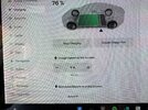
I’ve recently noticed our S and 3 engaging in an “Amp dance” with the local utility. The car will ramp up charge current towards the limit I set. If the voltage drops below some threshold, the car backs off. If voltage creeps back up - I believe as the utility feeds more power into the neighborhood transformer - then the car raises its draw a few more Amps.

The power transformer is buried in my next-door neighbor’s yard. Our house has 200 Amp service. Charging has a dedicated 100 Amp circuit. Two second-generation Tesla HPWCs cooperate to allow up to 80 Amps total charge rate. The 2017 Model S can pull up to 72 Amps.

We had the only EVs in the neighborhood for several years. Now I see three other Tesla driveways.
 
Does anyone know if these values are the same for the new Gen 2 UMCs? I'm looking at building some adapters and would be willing to take the extra step to have them throttle themselves than remember to change the draw in the car.
The UMC uses a small circuit which identifies the max current for the connector and possibly a temperature sensor. I have successfully removed one to replace the plug on a 16A (240V) blue commando adaptor - but it wasn't easy.

I wanted to go directly to a16A Neutrik PowerCon mains connector since I have a bunch of leads and adaptors that use these. This is what toughleads.co.uk call their letterbox connector. (They really are excellent - wish it had become the standard outdoor connector instead of commando/cee-form but I guess they're a lot more expensive to manufacture)

By making several careful cuts into the blue adaptor with a hacksaw I managed to locate the 'chip' and preserve as much as possible of the incoming cable.
About 25mm back from the back-plate of the connector there's a metal cable clamp. This is possibly the easiest place to cut in order to remove as much as possible of the wires as they can be pulled out from here. Beyond this point the wires spread out and can't be removed so easily.
The chip is a piece of 8x10mm circuit board positioned in a little blue plastic slot at the side of the connector in the area between the live and neutral pins. (Which makes sense if it also contains a temperature sensor.) If you cut 15 - 20mm back from the back plate of the connector you should be able to follow the blue & purple wires and cut away material until you have it. Better to leave black potting material attached to it than risk cutting the device itself. And you're going to need at least 4mm of wire still attached to be able to reconnect it.

Attaching the powercon plug was also tricky as the wires (32A rated?) only just fit into the terminals. I had to cut the insulation into rings and remove in stages as I pushed the wires in in-order to keep the strands bunched together. Re-attaching the chip was easy enough with some solder & heat-shrink tubing. There's actually plenty of room inside for it to fit (see picture.) The orange and white wires don't appear to be used.
Testing shows it all works. The max current you can set in the car is 16A. Obviously you must turn this down to the minimum *continuous* current rating of any of the connectors & cables you're using before the current starts flowing. Also be aware that the temperature sensor is not going to work so well surrounded by air instead of the potting material in the original plug. IMO this isn't a big issue. Its the domestic 13A 240v plugs and sockets that are the worst offenders for bad connections or loose fuses and they should be checked over the first hour of charging anyway.

With hindsight I think I was lucky this all worked. Even now I know exactly where the chip is I'm not sure I could be totally sure to extract another one without breaking it and wasting £35.

Anyway good luck
 

Attachments

  • plug1.jpg
    plug1.jpg
    363.6 KB · Views: 444
  • plug2.jpg
    plug2.jpg
    83.3 KB · Views: 98
  • plug3.jpg
    plug3.jpg
    1,002.7 KB · Views: 101
Last edited:
  • Informative
Reactions: Rocky_H
The UMC uses a small circuit which identifies the max current for the connector and possibly a temperature sensor. I have successfully removed one to replace the plug on a 16A (240V) blue commando adaptor - but it wasn't easy.

I wanted to go directly to a16A Neutrik PowerCon mains connector since I have a bunch of leads and adaptors that use these. This is what toughleads.co.uk call their letterbox connector. (They really are excellent - wish it had become the standard outdoor connector instead of commando/cee-form but I guess they're a lot more expensive to manufacture)

By making several careful cuts into the blue adaptor with a hacksaw I managed to locate the 'chip' and preserve as much as possible of the incoming cable.
About 25mm back from the back-plate of the connector there's a metal cable clamp. This is possibly the easiest place to cut in order to remove as much as possible of the wires as they can be pulled out from here. Beyond this point the wires spread out and can't be removed so easily.
The chip is a piece of 8x10mm circuit board positioned in a little blue plastic slot at the side of the connector in the area between the live and neutral pins. (Which makes sense if it also contains a temperature sensor.) If you cut 15 - 20mm back from the back plate of the connector you should be able to follow the blue & purple wires and cut away material until you have it. Better to leave black potting material attached to it than risk cutting the device itself. And you're going to need at least 4mm of wire still attached to be able to reconnect it.

Attaching the powercon plug was also tricky as the wires (32A rated?) only just fit into the terminals. I had to cut the insulation into rings and remove in stages as I pushed the wires in in-order to keep the strands bunched together. Re-attaching the chip was easy enough with some solder & heat-shrink tubing. There's actually plenty of room inside for it to fit (see picture.) The orange and white wires don't appear to be used.
Testing shows it all works. The max current you can set in the car is 16A. Obviously you must turn this down to the minimum *continuous* current rating of any of the connectors & cables you're using before the current starts flowing. Also be aware that the temperature sensor is not going to work so well surrounded by air instead of the potting material in the original plug. IMO this isn't a big issue. Its the domestic 13A 240v plugs and sockets that are the worst offenders for bad connections or loose fuses and they should be checked over the first hour of charging anyway.

With hindsight I think I was lucky this all worked. Even now I know exactly where the chip is I'm not sure I could be totally sure to extract another one without breaking it and wasting £35.

Anyway good luck
Is the chip easy to swap, to get up to 32 Amp
 
I was thinking of take the 16A plug and connect a 32A plug, just until I got the Tesla 32A original plug. Just to charge at 20-22A.
Just realize that power lost in a resistor is (I^2)*R. So going from 16a (which charges at a max of 12a) to your proposed 22a...

Is a factor of 484 / 144, or 336%

So your wires and connections in the circuit will be heating up more by a HUGE factor. This is a terrible idea if the circuit isn't designed for it.
 
  • Like
Reactions: mikeyg_ev
Just realize that power lost in a resistor is (I^2)*R. So going from 16a (which charges at a max of 12a) to your proposed 22a...

Is a factor of 484 / 144, or 336%

So your wires and connections in the circuit will be heating up more by a HUGE factor. This is a terrible idea if the circuit isn't designed for it.
My instalation is more than capable to handle that. Thanks for the warning.
Just want to tweak the 16a comando to charge a bit more fast until the original 32a comando is available. Here in europe it os nota available for a long time.
 
Just want to tweak the 16a comando to charge a bit more fast until the original 32a comando is available. Here in europe it os nota available for a long time.
Oh, blue commando and red commando. I am not as familiar with those European plug types, and that is unfortunate that the one you need is out of stock. Still, I think there would be a lot of better options than trying to perform surgery of changing the amp signal chips in the adapters. I don't even know how applicable that is to the European adapters. I think much better suggestions would be to try to find and buy a real cable or adapter from another seller.

There is a site a lot of U.S. Tesla owners buy from to get unusual kinds of adapters or things Tesla is out of. They do have a section on international adapters for other regions. The adapters they build do have the appropriate signaling in them to use the right amount of amps and plug directly into the Tesla charging cable, so they are a great source for these. I think I do see the one you are looking for, but it appears to be out of stock right now. They are usually pretty responsive, so you might contact them and see when they would have what you want. Or I'm sure there are other sites in Europe that sell Tesla adapters like this.