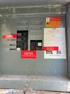
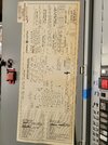
OK, that photo is clear enough to read the label. The model number is apparently very old as googling it turns up nothing. The label also doesn't explicitly say what type of breaker to use, or what the max breaker size is. It says MAINS 200 AMP MAX, but is that referring just to the bus rating, or does it mean a 200A breaker is available for that bus?
So based on the age and the potential difficulties of modifying it, replacing that with a new meter/disconnect (just one 200A breaker, no other breakers or buses) is a good option, on a technical basis. The downside is that you'd have to get PG&E involved to shut off the power, and so it would be expensive. If you choose this route, then your options are the same as option A below.
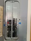
If you aren't replacing it, then the question is whether you or your electrician can track down what breakers that panel can take, whether they are available, and whether there is a 200A option. If you can get a 200A breaker, option A is to take out all the breakers and stick in one 200A breaker. That would comply with 230.71(B) (yes, that's the relevant limitation here).
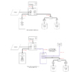
Then you run a 200A feeder to a splice area (which could be a separate enclosure, or could be the top of your garage panel if that's nearby). There the 50A PV conductors are spliced to the 200A feeder; depending on where those PV conductors originate and how they are protected there, you might need to set a 50A OCPD nearby to protect them. Then your garage panel (which you said has a 200A bus already) would get a 200A main breaker and be supplied by that 200A feeder. The feeder for the A/C units would be resupplied by a new breaker in the garage panel.
That would let you combine all your loads into a single 200A supply, rather than dealing with how it is currently split into (2) 100A supplies. The optional load calc would apply to the 200A feeder. You should have enough headroom on that calc to add a 40A or 50A circuit to the garage panel to supply your new EVSE. Also, moving the 50A feeder to/from the PV doesn't require Tesla; any sufficiently knowledgeable electrician can do that. [Getting them to properly update the location of the red labels might be a bit tricky, but then again Tesla wasn't careful with their labels anyway, as the "do not add loads" label on the service panel demonstrates.]
If you aren't replacing the service panel, and you are stuck with the (2) 100A breakers because of the limits of that panel or available breaker options, your best choice by far is the one I described of putting a 30A EVSE circuit on the 100A breaker presently supplying your A/C. Again, the details of that solution would depend on how everything downstream of that breaker is wired. I think you have provided the layout of that, but not the wire sizes or lengths.
Cheers, Wayne