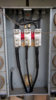
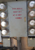
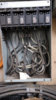
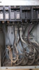
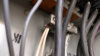
@eprosenx The neutral is fine. It is very hard to see in the pictures I posted but it is not on the enclosure. I'm attaching a side view close up so you can see it. It has a bar that goes up (see "neutral bar close up.jpg"). I also included a picture of the box with the 90A breaker ("90A breaker box.jpg"). It has the same cable as mine so I guess that's a code violation? I thought I could add a 90A or 100A breaker when I first started to look into this EV charger thing because that breaker was already upgraded but then I check the cable rating and I was wondering how could that be. I also took a picture of the sticker on the inside of the cover ("90A breaker cover.jpg").
I wish the builders of this place would have placed the breaker panel for my condo in the garage. The switch that posity suggested would have been perfect. But with the panel on the wall next to the bedroom ...it would be an eye sore with the red handle sticking out :-(.
I don't want to do anything that involves talking to the HOA. They are a bunch of dummies that say no to anything without even thinking. I was one of them for years until I got tired of being the odd guy out that would take time to investigate and talk to owners before the meetings. I quit years ago. Now I go there once in a while and I tell them how dumb they're doing things. So they ..ahem .. we don't like each other
")
. Besides the rules are that if something is only for my unit, it is my responsibility and they don't need to know.
Adding a new run of copper cable would be nice. But that would be pricey and I'm not sure where the service entrance cables are 100%. I'm trying to save as much as possible to get the LR Model 3 instead of the SR.
I'm still waiting for the electrician to get back to me. He said this week so we'll see what he says and what options are available.
Before I forget I'd like to thank you eprosenx for all the info you have provided. Also everyone else for all the good suggestions and comments.
Ok, great, glad to hear that neutral is not a dangerous situation. That bus bar is hiding in there pretty well! Thanks for taking the extra pictures.
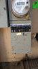
FWIW, the fact that there are eight different services without a common disconnect is interesting. I thought you are only allowed up to six, however, maybe older code was different or your local area had/has modified rules. Also, the building electrical meter has two independent 120v breakers and so that counts as two by itself. I additionally question whether terminating both neutral wires under the single screw is legit (probably not) but probably not that big a deal.
It looks like I am guessing each four pack of meters is good for a total of 250 amps (based on the sticker in the most recent pictures), so that is likely one reason they did 60a to each unit so that in aggregate you can't go over the 250 (though the chances that all four units are maxing out at the same time is very very low - I am sure NEC has some formula for calculating load for multiple MDU's on a common feed and allowing for some oversubscription).
I can not come up with any code allowance for that 90 amp breaker. That seems like a horrible idea. Maybe someone was reading the table for #4 *copper* wire? Also, I am curious if that breaker type is rated for use in that panelboard type?
One question just to confirm: The cable from the main meter base up to your condo is SE type as described in your original post. Does it also say it has a 75c or 90c rating on it somewhere? I just wanted to confirm. I am operating under the assumption that it is rated at least at 75c which gives it an ampacity of 65 amps.
My understanding of the code is that you are allowed to use the "next size up" rule which would allow you to replace the main breaker with a 70 amp one instead of a 65a one. Now you would still have to do the load calculations and make sure you fit within the 65a limit, but that would basically "unlock" another 5a of capacity (it does not seem like much, but on a 60a service everything helps!). Please check with a licensed electrician on this though.
At the end of the day, you need to do that load calculation based off the NEC formulas. I need to read more up on that. ;-) I have just used the various ones online, but they seem to differ from each other.
I think you will either end up with:
* A 20a 240v receptacle (12awg), a 30a 240v receptacle (10awg - dryer plug), or a 50a 240v receptacle (6awg in most cases, unless in conduit and then sometimes can do 8 awg - NEMA 14-50 or 6-50 though 14-50 is more common). Each of these solutions would use your UMC.
* Then the other option would be a wall connector, which the nice thing about that would be the ability to crank up or down the allowed amps as long as you wired it with sufficient ampacity wire. You might start it out set to 16a, but once you gained historical data on usage you might find you could charge at higher rates safely. Maybe say wire a Wall Connector up with 6awg and put it on a 50a breaker. (remember the load calculation is based on what the rotary dial is set to - NOT the breaker).
You might want to consider a Sense energy monitor in your main panel so you can keep tabs on your power usage. I personally put my Sense on its own dedicated 240v breaker just to make it as clean an install as possible. This may be easier if you replace your main panel.
Note that the transfer switch is not a bad idea if you are running up against load calculation issues, though I would find it annoying to not be able to charge my car when it was hot out. A 20a 240v plug without having to do the transfer switch might be less annoying than having to manually transfer all the time. Or if you wanted to get really tricky you could do both a 6-20 receptacle on its own circuit (if the load calc allowed), PLUS put the transfer switch on the AC and then wire it to a 14-50, a 6-50, or a HPWC. Then you could have "slowish" charging while running the AC, or "fastish" charging at times of year you did not need the AC. You would do the load calc as the greater of either the AC running plus the car at 16a on that 20a circuit, OR just the car by itself drawing 32a if using the UMC on the 14-50 or 6-50, or if a HPWC then whatever you chose to set that to.
I will call out that a disconnect right next to the HPWC is NOT always required for the HPWC in 2017 NEC. You do need a disconnect that can be "locked off" if the HPWC is fed from a circuit *over* 60a (or greater than 150v to ground - which is never the case in standard US residential service). My understanding is that you can buy a little metal clip for the breaker panel to allow it to be locked off which then counts as the disconnect. As far as I know the code calls for "readily accessible" disconnect, but it does NOT say it has to be within a certain number of feet or be "visible". Now some jurisdictions may modify this rule to be more stringent, or they may interpret "readily accessible" differently.
My take on it is that HPWC's don't have anything in them that really needs servicing. Local disconnects make all the sense in the world for HVAC units where techs are in and out of them all the time and they may not have access inside or to the electrical panel. If you are coming to work on a HPWC you are probably an electrician and have access to the panel...
Let us know what you end up doing! You have a rather unique challenge. ;-)