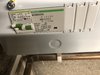
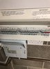
The TWC is outside next to the garage (see pic) with the CU in the garage. I'm hoping that the electrician will move it inside the garage (which I've interpreted from your reply means no Earth Rod/PEN needed) and therefore should be cheaper for them.
I'll keep the forum updated. Thanks again all.
Good photos, thanks. Relocating the TWC inside the garage is fine, as long as the car is only charged when in the garage, and the tethered cable cannot reach a car parked outside.
There would seem to be three options:
1. Relocate the TWC inside the garage, to a location where the cable can reach the car when parked in there OK, but cannot reach a car parked outside. Remove the 32 A RCBO and blank that slot in the CU. Install a new small CU adjacent to the existing CU, that contains a main switch, a Type B RCD and a 32 A or 40 A MCB. Feed this from Henley blocks fitted to the existing tails that supply the main CU, with additional 25mm tails running to the new CU. Connect the TWC to this new secondary CU. This option doesn't require open PEN fault protection, as the car would be considered to be within the PME "earthed envelope", so all exposed conductive parts, including the garage floor, would be considered to be equipotential.
2. Leave the TWC outside, where it is currently located, but check that it isn't practical to be able to touch the car bodywork when parked outside and the exposed conductive parts in the garage, i.e. the pipes, tap etc. 2m is a sensible separation distance between two earthing systems. Install an earth electrode adjacent to the TWC, in a safe location, well away from incoming services to the house etc. As above, install a small secondary CU containing a main switch, Type B RCD and sutable MCB, ensuring that the two earthing systems (TT for the TWC and PME for the house) are kept separate.
3. Keep the TWC in its present location and install a secondary CU that includes both DC tolerant earth leakage protection and open PEN fault protection. There are then no concerns with separate earthing systems needing to be kept apart by 2m and this may well be cheaper. Ecoharmony do a suitable small box that can do this:
EVSE Connection Centre with PEN Loss detection - IP65
If it were me, then I'd go for option 3, and connect that protection box to the incoming meter tails via a couple of Henley blocks, remove the 32 A RCBO from the main CU and blank that slot and re-route the TWC cable to the Ecoharmony box. It's only an hour or two's work, and would make for a neat and safe installation.