Welcome to Tesla Motors Club
Discuss Tesla's Model S, Model 3, Model X, Model Y, Cybertruck, Roadster and More.
Register

Just had 9.8kw Solar+2PW installed, have some noob questions.

This site may earn commission on affiliate links.
And one other weird problem. I definitely do NOT have PTO yet and "Permission to Export" is set to "No"... but according to the Sense meter, the Gateway is sending power back to the grid.
When the grid CTs are misconfigured, it can't do the right thing. You should point out the fact that the system is illegally exporting to the Tesla support people, but they may not care to take care of it any faster...
 
tl;dr: It now works. The installers added a remote Neurio transmitter in the main panel that was redundant double-counting the total energy consumed. Neurio removed.


Well, Tesla was here today to meet with the town inspector, and arrived about 90 minutes before the inspector did.

I showed him the erratic power flow behavior I posted about above, and he agreed that was very strange. He got Tesla tech support on the line, and to make a really long story short, it took three of us and about two hours to finally get it resolved.

At first the tech support guy said there's a new (and still unfixed) bug in the latest TEG firmware causing the double readings from the CTs. But as we all went through the design and layout, they realized that the Neurio remote sensors on the main 200A service line weren't actually necessary. Between the remote CTs and the CTs inside the gateway (they're called the "X" and "Y" sensors), it was double/over-counting the total home power draw. The remote Neurio CTs measured everything, and the GW CTs measuring the backup load panel so the total power draw was being over-measured.

Once we removed the remote CTs from the main service lines, instantly the readings became non-erratic and the system started to function normally and solar was then providing 100% of the house draw (more on this later).

So then the Tesla guy removed the Neurio from the non-backup-loads panel, and suddenly the solar turned completely off. We powered up the Neurio again (still with the CTs removed) and the solar started producing again. So the GW configuration was still looking for the remote Neurio before engaging the inverter. So we went into the configuration wizard on the Tesla guy's phone and removed the remote sensor from the config.

Then we waited and waited and waited, but the solar never kicked on again. We put the system into off-grid mode to draw down the PWs to 98%, but even still, the solar would not kick on. So we called tech support again, and while they were looking into it, the inverter kicked on. Turns out (and most of you know this already), when the PWs are full, and I don't have PTO/export yet, the inverter shuts down the solar production. Anyway, I guess one of the two PWs dropped below some threashold and the inverter was able to kick on and supply the house with power again.

The only downside to this entire experience is that now the Tesla app and power flows and the grafana web monitoring tools do not include my non-backup-loads panel. Everything now only reports the backup-loads panel as-if that was the 'entire house'. I can live with that, I suppose. My SENSE meter can measure the whole-house loads, except it doesn't handle net metering at all.


They may have misconfigured the setup of the CTs so that it is using the sum of the remote CT they added to your panel and the CT inside the GW2.

Pretty darn close! They were not misconfigured, they were totally not necessary!
 
I'm not sure if that was an option they would have considered.
They should. This is essentially how my system works. The difference is that my Gateway 1 system has the factory installed Neurio inside the Gateway to measure Grid and Solar. My Grid CTs were moved from the input of the Backup Switch to the main panel conductors between the main breaker and the main panel bus. The installer had to extend the wires through the conduit joining the main panel and the Gateway. The Gateway 2 Grid CTs are integrated and cannot be moved/removed. They can only be disabled for Grid measurement.
 
  • Like
Reactions: yblaser and Vines
My inverter also has a small coolant leak (also reported to support and they're looking into it):

Mine is leaking too (installed yesterday). My app does not have the request service button available yet. How did you get a hold of them?

Tim
IMG_4021.jpeg
 
Mine is leaking too (installed yesterday). My app does not have the request service button available yet. How did you get a hold of them?

Tim

Should this happen to someone else... I posted this on a Facebook group and got the following response.

"Just need to tighten hex bolt inside door top right corner. Sometimes coolant leaks when bolt is not torqued down all the way. Quick fix. Installers should have tightened all bolts but must have slipped their mind. Does not always happen but have seen it before. Hex bolt located on top right corner by fan once you open inverter door, using push in latch at the bottom center of the inverter door. Open it up and tighten the hex bolt that is gold. Should take care of it."

I just checked it out and the source of the leak does seem to be coming from the hex bolt. I had JUST purchased a new set of wrenches maybe 3 weeks ago. Grabbed my brand new 10mm and was able to torque that bolt maybe an 1/8th turn. Will head back out there in a couple hours to see if that did the trick. This gentleman certainly seems knowledgable, and I assume that's going to be the end of the leak.

I'll come repot back if it ends up being something else, but pretty sure this ones solved.

Tim
 
Unless this was your agreement initially I also consider it unacceptable to leave out the non backup loads from measurement. It just sounds like they don't really understand what the metering needs to do.

Missing or misconfigured CTs is so common it's ridiculous. And something so simple that you'd think they'd be able to train their crews properly.
 
Missing or misconfigured CTs is so common it's ridiculous. And something so simple that you'd think they'd be able to train their crews properly.
Its actually hard/annoying enough that many electrical engineers fail to do it right.

Configuring the CTs correctly require thorough understanding of the home's single line diagram which I don't think everyone is good enough at doing. The main thing is double checking the actual energy flow to see if it makes sense which isn't always obvious as everyone here has noted.
 
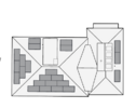
Quick noob question. I have 23 400w panels for a 9.2kW system on all four sides of our roof.
There are no trees or any other blockages.

1655670595923.png


The bottom face with the most panels (10) is facing south-south-west.
During the peak summer days, what do you think the max kWs I'd be able to get from this system? Is it really 9.2kW?

So far, the max output I've seen is 7.28kW -- which just so happens was today.

Being June 21st the longest day of the year just a couple of days away, is this nearly the peak possible output due to the slant of the other roof faces? Or should I see maybe a little more as we get into the hotter summer months? Below is the graph of the four strings and voltage output (The ABCD strings are labeled in the above diagram).

thanks.

1655669756326.png
 

Attachments

  • 1655669420732.png
    1655669420732.png
    22.1 KB · Views: 57
Last edited:
Quick noob question. I have 23 400w panels for a 9.2kW system on all four sides of our roof.
There are no trees or any other blockages.

View attachment 818574

The bottom face with the most panels (10) is facing south-south-west.
During the peak summer days, what do you think the max kWs I'd be able to get from this system? Is it really 9.2kW?

So far, the max output I've seen is 7.28kW -- which just so happens was today.

Being June 21st the longest day of the year just a couple of days away, is this nearly the peak possible output due to the slant of the other roof faces? Or should I see maybe a little more as we get into the hotter summer months? Below is the graph of the four strings and voltage output (The ABCD strings are labeled in the above diagram).

thanks.

View attachment 818569
Maximum output is defined by how large your PV inverter is.

If this is connected to a 7.6 kW inverter then that is all you would ever produce (at 240v) even with perfect irradiance on every plane.

Likely the maximum you will get will happen in the afternoon as the sun is getting a pretty good straight shot on your south and west roof planes. I think if you have a 7.6 kW inverter then 7.3 kW is pretty good.

You don't mention which panel model but checking the data, its likely about 370w of actual output when you consider the effects of heat. Even if all your panels were perfectly south and at the optimism inclination at your attitude they would only produce 8510 DC PTC watts. Once you consider inverter efficency of 97% its only 8255 w. Since you really have 4 different azimuths, you will never see that peak.

I just ignored your north modules and multiplied the remaining modules by 370w assumed PTC, and came up with 7030w. I think your system is probably producing well if you peak at 7.3 kW.