After years of dealing with the coolant pump running almost 24/7 here in hot sunny Florida, I finally decided to do something about it. Since the Roadster just taps into the existing air conditioning system for ESS cooling, I just connected 12V to the ESS cooling solenoid. Now I can activate battery cooling anytime I want. No more having to plug in or shut down the APS to get the car to go to sleep. I had put this off for a long time, dreading having to disassemble the dash. But after it ended up being fairly simple, I wish I had done it years ago.
You will just need an on/off switch and some 2 conductor wire (speaker wire works good).
For tools you need a phillips screwdriver, a 8mm socket or nut driver, and a soldering iron.
Step1) Shut down the APS. If you don't know how to do this, maybe you shouldn't attempt this mod.
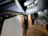
Step 2) The A/C control module is located in the front of the center console, behind the 12V power outlet and the USB download port. You need to remove the cover on the right side. There are four retainers holding the cover with the power outlet (two on each side) and two more in the side cover. The plastic retainers have a phillips head screw that you need to back out about 1/4 of an inch, and then pull on the screw to pop out the retainer. If you completely remove the screw, you will have to pry out the remaining expanding shell, so its easier to just back out the screw.

Left side showing the two retainers in the front cover
 Right side showing the four retainers
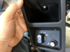
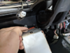
 Right side cover removed. You can see what the retainers look like. The front cover gets wedged against the bottom of the dash, so you need to work the cover (pry gently) out towards the front of the car
Step 3) Remove the A/C control module. It is attached with three 8mm nuts - one on the top left and two on the right. The two on right (forward) you do not have to remove all the way, as the mounting ears on the module are slotted
 A/C module removed
 Closeup of the three studs securing the A/C module. Again, the two on the right you do not have to remove fully, as they are a pain to get the nuts back on, since you have to do it by feel.
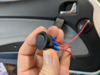
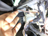
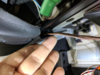
Step 4) Locate the wires to connect the switch. The rear connector (closest to you) has the wires you need to connect to. The connector is clearly labeled - A through K, rows 1,2 and 3. The black wire with the red stripe is the output for the ESS cooling solenoid - terminal H3. The main power input from the APS is the larger tan wire on terminal J1 (or J2 - both tan wires are power). You just need to connect a switch between the two.

Rear connector showing tan (power), and black/red (solenoid) wires.
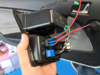
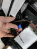
Step 5) Strip back a little insulation from each of the tan and black/red wires and solder your supplied wire to each. Insulate with tape - liquid electrical tape makes it easy, as it's cramped down there.

I installed an in-line fuse on the power lead just to be safe
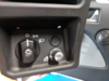
Step 6) Route the wires to wherever you want your switch and connect the wires. Secure the wires with zip ties to keep them from rubbing on anything.

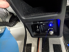
I mounted mine in the iPod holder.
Step 7) Test it by turning the APS back on and listen for the click of the solenoid when you flip the switch.
Step 8) Reassemble in the reverse order.
Now anytime you want to cool down the battery, just turn on the A/C and flip the switch. Anything below 30'C and the car will go to sleep after you power down. I find it nice to be able to keep the ESS temp under the point where the car demands an ESS cooldown and robs you of the cabin A/C. I just flip the switch for a minute to keep the battery temp in check, and turn it off when I notice the cabin air start to get warmer.
While I obtained power from the APS feed to the A/C module (which is always on when the car is awake), you could get power from the key on circuit to avoid solenoid activation when the key is off. The key on feed to the A/C module is terminal F2, which is a small green wire. I didn't want to put a load on that circuit, so I used the APS feed which is already designed to power everything. You could get key on power from the radio or somewhere else, but that would involve more disassembly, and I wanted to keep it simple. You might consider using a lighted switch so you can see when the cooling is on, but with the decrease in the cabin A/C output, its pretty obvious. I suppose if you left it on long enough you might eventually get condensation inside the ESS - and that would be bad. So use this info at your own risk.
You will just need an on/off switch and some 2 conductor wire (speaker wire works good).
For tools you need a phillips screwdriver, a 8mm socket or nut driver, and a soldering iron.
Step1) Shut down the APS. If you don't know how to do this, maybe you shouldn't attempt this mod.
Step 2) The A/C control module is located in the front of the center console, behind the 12V power outlet and the USB download port. You need to remove the cover on the right side. There are four retainers holding the cover with the power outlet (two on each side) and two more in the side cover. The plastic retainers have a phillips head screw that you need to back out about 1/4 of an inch, and then pull on the screw to pop out the retainer. If you completely remove the screw, you will have to pry out the remaining expanding shell, so its easier to just back out the screw.
Left side showing the two retainers in the front cover
Step 3) Remove the A/C control module. It is attached with three 8mm nuts - one on the top left and two on the right. The two on right (forward) you do not have to remove all the way, as the mounting ears on the module are slotted
Step 4) Locate the wires to connect the switch. The rear connector (closest to you) has the wires you need to connect to. The connector is clearly labeled - A through K, rows 1,2 and 3. The black wire with the red stripe is the output for the ESS cooling solenoid - terminal H3. The main power input from the APS is the larger tan wire on terminal J1 (or J2 - both tan wires are power). You just need to connect a switch between the two.
Rear connector showing tan (power), and black/red (solenoid) wires.
Step 5) Strip back a little insulation from each of the tan and black/red wires and solder your supplied wire to each. Insulate with tape - liquid electrical tape makes it easy, as it's cramped down there.
I installed an in-line fuse on the power lead just to be safe
Step 6) Route the wires to wherever you want your switch and connect the wires. Secure the wires with zip ties to keep them from rubbing on anything.
I mounted mine in the iPod holder.
Step 7) Test it by turning the APS back on and listen for the click of the solenoid when you flip the switch.
Step 8) Reassemble in the reverse order.
Now anytime you want to cool down the battery, just turn on the A/C and flip the switch. Anything below 30'C and the car will go to sleep after you power down. I find it nice to be able to keep the ESS temp under the point where the car demands an ESS cooldown and robs you of the cabin A/C. I just flip the switch for a minute to keep the battery temp in check, and turn it off when I notice the cabin air start to get warmer.
While I obtained power from the APS feed to the A/C module (which is always on when the car is awake), you could get power from the key on circuit to avoid solenoid activation when the key is off. The key on feed to the A/C module is terminal F2, which is a small green wire. I didn't want to put a load on that circuit, so I used the APS feed which is already designed to power everything. You could get key on power from the radio or somewhere else, but that would involve more disassembly, and I wanted to keep it simple. You might consider using a lighted switch so you can see when the cooling is on, but with the decrease in the cabin A/C output, its pretty obvious. I suppose if you left it on long enough you might eventually get condensation inside the ESS - and that would be bad. So use this info at your own risk.