I wired a little electricity power meter I bought on Amazon to my EVSE. I'm charging at work now that they installed a 14-50 outlet for me (nice boss I have, although it took a year of wheedling). I'm going to pay for my electricity. Boss says not to worry about it, but when he sees I've used 2 MWH of electricity after a few years he may let me! This is actually for my Volt, as I don't charge the Model S at work (no need of course). But you could easily wire one of these meters to a 14-50 outlet used for a Tesla to allow you to pay for your power used at work. The meter was about $20 on amazon. It has four connections - two for the current transducer and two for the voltage. Very simple to connect.


Welcome to Tesla Motors Club
Discuss Tesla's Model S, Model 3, Model X, Model Y, Cybertruck, Roadster and More.
Register
Install the app
How to install the app on iOS
You can install our site as a web app on your iOS device by utilizing the Add to Home Screen feature in Safari. Please see this thread for more details on this.
Note: This feature may not be available in some browsers.
-
Want to remove ads? Register an account and login to see fewer ads, and become a Supporting Member to remove almost all ads.
You are using an out of date browser. It may not display this or other websites correctly.
You should upgrade or use an alternative browser.
You should upgrade or use an alternative browser.
AB4EJ
Member
Very neat. It looks like fairly small gauge cable you are using. How much current could the meter take? Typical Tesla home charging is 40 A (or 80 A if you use the high-power approach). What is the max gauge cable the connectors can handle?This is a better picture of the meter.View attachment 177251
These 'power meters' use current transducers to measure the current flow and typically converts it to a low voltage. The transducer clamps around the current carrying conductor and measures the current flow by the flux field. The meter then knows the ratio and adjusts the readings to be primary units. The only problem is that the transducers are typically +/- 5% accurate. Some are a bit better. Good for a ballpark reading.Very neat. It looks like fairly small gauge cable you are using. How much current could the meter take? Typical Tesla home charging is 40 A (or 80 A if you use the high-power approach). What is the max gauge cable the connectors can handle?
Very neat. It looks like fairly small gauge cable you are using. How much current could the meter take? Typical Tesla home charging is 40 A (or 80 A if you use the high-power approach). What is the max gauge cable the connectors can handle?
No power goes through the meter. Think of it like a hand-held meter you have at home to measure voltage. With that you put the two probes on the two points you want to check and you get a voltage reading - you are not "in series" with the current loop and so you're not carrying the current of the two wires you're checking. Same with this meter.
This meter has a current transducer, which is just a round magnet. You have to put one leg of the loop you are checking through the magnet. Two leads connect to the magnet so the meter can sense the current, but again you are not involved in the current flow to the car, so there is very little current in these wires.
So, the four wires you see going to the meter are carrying a very tiny amount of power. I think the wires are 18 ga.
Looks like you followed the NEC to a tee! lolHere is a picture of where I cut into the cable to attach the meter wires. You can see the magnet. It looks kind of like a snake that swallowed a donut.View attachment 177257
")
BrokerDon
Active Member
Thanks for the link, I think I'll order a juiceplug. It doesn't ship until June though, so my solution is good for now. Do you have any of their products? I can't mount anything on the wall, so that part of it is out for me.JuiceBox offers several better solutions:Electric Motor Werks, Inc. - JuiceBox EV Charging Stations
Boatguy
Active Member
I have one for my i3. You can read the voltage, current, real time power from the app. You can see all that plus charge history on the web site. No DIY necessary, though it does need wifi.JuiceBox offers several better solutions:Electric Motor Werks, Inc. - JuiceBox EV Charging Stations
I have one for my i3. You can read the voltage, current, real time power from the app. You can see all that plus charge history on the web site. No DIY necessary, though it does need wifi.
Which one do you have? Any pics available? I can't use one that mounts on the wall because my boss wouldn't want a box there. It took forever just to get the outlet installed.
Boatguy
Active Member
I have the "Smart" 40amp which has a wifi connection. They also make one without. It's just an aluminum box with two cables, one to plug into the wall, and one to plug into the car. Lots of pics and more at eMotorWerks.Which one do you have? Any pics available? I can't use one that mounts on the wall because my boss wouldn't want a box there. It took forever just to get the outlet installed.
davewill
Active Member
I think your original meter is just fine, but I would have put it in a project box inline with the plug instead of that mass of electrical tape. As it is now, some one could snag those two exposed wires and you'd have 240v exposed. Also it doesn't look very weatherproof is.
An alternative would be a box with a 14-50 receptacle and plug on it so you could leave it off in bad weather.
An alternative would be a box with a 14-50 receptacle and plug on it so you could leave it off in bad weather.
ReversePolarity
Member
Pretty neat... is this basically for calculating the "power loss" or what not when charging a battery?
gkalexdc
Member
Love this. I saw this meter on Amazon, and couldn't figure out HOW to connect it. A schematic perhaps would help me.I wired a little electricity power meter I bought on Amazon to my EVSE. I'm charging at work now that they installed a 14-50 outlet for me (nice boss I have, although it took a year of wheedling). I'm going to pay for my electricity. Boss says not to worry about it, but when he sees I've used 2 MWH of electricity after a few years he may let me! This is actually for my Volt, as I don't charge the Model S at work (no need of course). But you could easily wire one of these meters to a 14-50 outlet used for a Tesla to allow you to pay for your power used at work. The meter was about $20 on amazon. It has four connections - two for the current transducer and two for the voltage. Very simple to connect.View attachment 177246 View attachment 177247
Are all the connections on the 240 supply before the ESVE?? I couldn't tell from the pictures. Can you help me ??
Dr Alex
Houston
Love this. I saw this meter on Amazon, and couldn't figure out HOW to connect it. A schematic perhaps would help me.
Are all the connections on the 240 supply before the ESVE?? I couldn't tell from the pictures. Can you help me ??
Dr Alex
Houston
Have you done much wiring? Any little wiring projects in the home? You need a rudimentary understanding of "hot" "neutral" and "ground", or I wouldn't attempt it. But if you know what those three terms mean you are good to go. The meter comes with a schematic.
Here's a brief description of the connections as I made them. And this is from memory, so I could screw this up, but it should give you the basic idea.
The meter comes with a ring-shaped magnet. You have to run either the "hot" or "neutral" through it. NOT BOTH. Only one or the other.
The ring-shaped magnet has two wires attached to it when you get it. You don't have to attach them. You just land them on the meter, based on the schematic that comes with the meter. The meter has 4 terminals, and this occupies two of them. So, with the "hot" or "neutral" going through the magnet, the meter can now read the current flow.
The meter has to sense the voltage. To do this you connect a wire to the "hot" and land it on the meter, again just landing it where the schematic shows. And you also connect a wire to the "neutral" and land it on the meter. These two wires are identical to the probes on a home electrical meter that you would touch to a pair of wires to see if they had voltage, or touch to the terminals on a battery to test its voltage.
When I say "you connect a wire to the 'hot'", one way to do this would be to cut the "hot" wire, and then use a wire nut to connect the two ends you just cut plus a third wire. Then you land the other end of the third wire on the meter, so now the meter is connected to the "hot" and can sense it. You can do the same with the "neutral".
Hope this helps. If you buy the meter and can't connect it, return it to Amazon and nothing lost!
One note: I used 18 ga wire for my voltage sensing wires mentioned above. Don't use bigger wire as the meter won't really take it, and if you short the voltage you'll destroy the meter. I also used silicone to seal the connections at the meter for a little home-grown water proofing.
gkalexdc
Member
Have you done much wiring? Any little wiring projects in the home? You need a rudimentary understanding of "hot" "neutral" and "ground", or I wouldn't attempt it. But if you know what those three terms mean you are good to go. The meter comes with a schematic.
Here's a brief description of the connections as I made them. And this is from memory, so I could screw this up, but it should give you the basic idea.
The meter comes with a ring-shaped magnet. You have to run either the "hot" or "neutral" through it. NOT BOTH. Only one or the other.
The ring-shaped magnet has two wires attached to it when you get it. You don't have to attach them. You just land them on the meter, based on the schematic that comes with the meter. The meter has 4 terminals, and this occupies two of them. So, with the "hot" or "neutral" going through the magnet, the meter can now read the current flow.
The meter has to sense the voltage. To do this you connect a wire to the "hot" and land it on the meter, again just landing it where the schematic shows. And you also connect a wire to the "neutral" and land it on the meter. These two wires are identical to the probes on a home electrical meter that you would touch to a pair of wires to see if they had voltage, or touch to the terminals on a battery to test its voltage.
When I say "you connect a wire to the 'hot'", one way to do this would be to cut the "hot" wire, and then use a wire nut to connect the two ends you just cut plus a third wire. Then you land the other end of the third wire on the meter, so now the meter is connected to the "hot" and can sense it. You can do the same with the "neutral".
Hope this helps. If you buy the meter and can't connect it, return it to Amazon and nothing lost!
One note: I used 18 ga wire for my voltage sensing wires mentioned above. Don't use bigger wire as the meter won't really take it, and if you short the voltage you'll destroy the meter. I also used silicone to seal the connections at the meter for a little home-grown water proofing.
Attachments
gkalexdc
Member
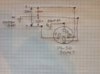
Thank you for your reply. I have seen the diagram on these meters you have used in your example. Since there are two hot legs and a neutral on a 14-50 socket, shown here. I was just wondering how to wire the two voltage wires to get the 240v reading, since a connection to just X or Y and one to G would read 125v. How to wire the leads for a 240 reading.
I now ( I think) understand you are not doing any monitoring on any thing from the ESVE to the car, that you are monitoring the 240 gang into the ESVE.
Do I have that part right?
Any help on how to wire on the above schematic of the 14-50 would be really appreciated.
Thanks,
Dr Alex
Houston
I now ( I think) understand you are not doing any monitoring on any thing from the ESVE to the car, that you are monitoring the 240 gang into the ESVE.
Do I have that part right?
Any help on how to wire on the above schematic of the 14-50 would be really appreciated.
Thanks,
Dr Alex
Houston
Thank you for your reply. I have seen the diagram on these meters you have used in your example. Since there are two hot legs and a neutral on a 14-50 socket, shown here. I was just wondering how to wire the two voltage wires to get the 240v reading, since a connection to just X or Y and one to G would read 125v. How to wire the leads for a 240 reading.
I now ( I think) understand you are not doing any monitoring on any thing from the ESVE to the car, that you are monitoring the 240 gang into the ESVE.
Do I have that part right?
Any help on how to wire on the above schematic of the 14-50 would be really appreciated.
Thanks,
Dr Alex
Houston
My meter is monitoring the voltage and power flowing from the circuit breaker in the panel to the 14-50 outlet, which is ALSO the exact same voltage and power flowing from the EVSE plugged into that socket and going to the car. I'm assuming nothing else is on the circuit.
Similar threads
- Replies
- 4
- Views
- 145
- Question
- Replies
- 8
- Views
- 2K
- Replies
- 10
- Views
- 2K
- Replies
- 19
- Views
- 686