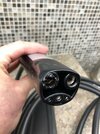
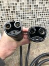
I’m hoping someone can provide some guidance on this since Tesla Toronto East Service Centre hasn’t been able to solve this problem yet. I have a 2015 Model S that I’ve been charging daily for well over 6 years in my garage using a NEMA 14-50 AMP recepticle. Early in November I was unable to detach the mobile connector cable from the car as the connection melted and was fused into the charging port. The car had to be towed to the Tesla service centre and resulted in the charge port and internal cable being replaced ($3,000+ repair) and I bought a new mobile connector cable. I spoke to the Technician who repaired my car to understand what exactly happened and came away with the understanding the issue was a result of a faulty first generation mobile connector charging cable. About 2 weeks later it happened again with the new cable but this time with some difficulty, I was able to disconnect the mobile adaptor from my Model S charge port. I drove the car back into the Tesla service centre to have it checked out and they claimed it must be my NEMA electrical connection that was faulty. So I purchased a second new mobile connector cable and had an electrician check the charging setup and he found everything was OK with no evidence of malfunction. Just to be on the safe side I had him replace the NEMA plug. The first time charging my car using this second new cable and the replaced NEMA outlet, it once again melted the cable connection in the charging port. I should mention that I’ve been charging lately at local Tesla Superchargers with no apparent problems. So it’s back to the Tesla Service Centre for the third time because I have to believe the issue is with the car and not with my home charging connection. I’ve included pictures of the 2 new mobile connector cables that have been melted on the same side. Anyone else have this experience or have any ideas of what might be happening in the car? Any other tips on how to proceed with Tesla?


Welcome to Tesla Motors Club
Discuss Tesla's Model S, Model 3, Model X, Model Y, Cybertruck, Roadster and More.
Register
Install the app
How to install the app on iOS
You can install our site as a web app on your iOS device by utilizing the Add to Home Screen feature in Safari. Please see this thread for more details on this.
Note: This feature may not be available in some browsers.
-
Want to remove ads? Register an account and login to see fewer ads, and become a Supporting Member to remove almost all ads.
You are using an out of date browser. It may not display this or other websites correctly.
You should upgrade or use an alternative browser.
You should upgrade or use an alternative browser.
Model S Mobile Connector Melts 3 Times Even After Tesla Service Repair
- Thread starter Steve W
- Start date

The car, and I thought the connector, should limit power or shut down well before this occurs. The Gen 3 connector should also protect against this. It sure seems like it is the car at fault, but I do not understand why the other protection should also not be preventing this. I would file a safety report at the NHTSA when you figure this out so that they can see if this happens with others to keep us all safe.
Upvote
0
I would really like to know what volts and amps the car is showing on the charging screen when you are doing this. There is a process where the external charging cord is generating a signal of what maximum amount of amps are available. The onboard charging system in the car is supposed to detect that and only pull up to that level of amps. But what if something in the car's onboard charger is malfunctioning and not complying with that amp limit? What if it is trying to pull 40 or 48A, when the charging cable isn't made to support that?
Upvote
0
bedoig
Member
Definitely an interesting one-off situation, don't think I've ever seen anything like this before. @Rocky_H - even if the car was somehow requesting more amps than allowed it would indicate a multi-point failure with the car and UMC though, right? The UMC should be dictating max amps drawn and never exceed that (otherwise you start flipping breakers, melting outlets, burning house wiring, etc). Even then it seems far-fetched that any of the UMC's regardless of generation start melting the UMC-->vehicle plug at 32 vs 40 amps when even supercharges all seem to use the same 'evse'-to-car connection (maybe there's cooling somewhere in there in 250kw superchargers?). Still seems like it's got to be an issue with resistance in the car receptacle, but OP says that was replaced and happened with several different UMCs? Weird.
Upvote
0
Yeah, it's a far-fetched guess, but this is unfamiliar and was stumping me. I wanted to see the car's reading of amps, but if he didn't take note of it the times it was breaking things before, it don't think he would want to do it again just to take a reading.Definitely an interesting one-off situation, don't think I've ever seen anything like this before. @Rocky_H - even if the car was somehow requesting more amps than allowed it would indicate a multi-point failure with the car and UMC though, right?
Well, yes, the UMC sends the signal of what the limit is supposed to be. But then the charging system in the car is supposed to honor that limit. I don't know what would happen if it didn't. If it tried to pull more, I think something in the UMC should break or trip if it tries to go over 32A.The UMC should be dictating max amps drawn and never exceed that (otherwise you start flipping breakers, melting outlets, burning house wiring, etc).
That is a different deal and doesn't use the same kind of signaling methods. All of the charging equipment is external to the car and then bypasses the onboard chargers. But @Steve W said that he has used Superchargers after this and didn't have a problem, and that should be much higher current and heat. So that plug handle didn't have an issue, and the port didn't have an issue. I think it was something with AC charging and the UMC plug that is causing that plug to overheat and melt. It has thinner wiring in that cable than Supercharger handles.when even supercharges all seem to use the same 'evse'-to-car connection (maybe there's cooling somewhere in there in 250kw superchargers?).
Upvote
0
ucmndd
Well-Known Member
That’s super wild, I’m stumped. Between new UMCs and a new charge port everything physically related to the connection on that pin should have been replaced.
Interesting that it’s the same pin every time… that would freak me out. Seems like something related to the onboard charger is allowing the car to draw more current than it should be able to… or there’s a loose connection somewhere further down the cable that’s causing the whole thing to heat up and melt the plastic connection upstream.
Interesting that it’s the same pin every time… that would freak me out. Seems like something related to the onboard charger is allowing the car to draw more current than it should be able to… or there’s a loose connection somewhere further down the cable that’s causing the whole thing to heat up and melt the plastic connection upstream.
Upvote
0
Huachipato
Member
I suspect there is some impedance in the charger port somewhere. I'd be curious what your houses voltage is and what voltage your car sees.
Upvote
0
That doesn't fit the data though. It melted the first time, and then the charge port was replaced, and it still melted a second and third time.I suspect there is some impedance in the charger port somewhere. I'd be curious what your houses voltage is and what voltage your car sees.
Upvote
0
Huachipato
Member
How does it not? In the images you can clearly see the melted port is dirty, and the middle clear plastic rods have clearly been overheated. The dirtier it gets the more impedance will build up which leads to more heat which leads to melting stuff... If there is impedance (electrical resistance) there, it could be detected as a drop in voltage.
Upvote
0
I thought I explained that really clearly. You said it's a problem with the port. But the port had already been replaced after the first time and was a new port during the 2nd and 3rd melting events. So the port was already eliminated as the problem when the replaced new one was also involved in further melting events.How does it not?
And that would have only possibly been relevant if it had happened only once. But when the port was replaced with a brand new clean one, and then it also had this overheating and melting event two more times with a brand new clean port, that showed that the problem was definitely somewhere else.In the images you can clearly see the melted port is dirty, and the middle clear plastic rods have clearly been overheated. The dirtier it gets the more impedance will build up which leads to more heat which leads to melting stuff... If there is impedance (electrical resistance) there, it could be detected as a drop in voltage.
Upvote
0
No, I didn't say there is no impedance. There could be some somewhere but not where you said. I have plenty of curiosity but it's about other things, not where you said you think the problem is.You are stating that there is no impedance cause the port and charger were changed without any curiosity to measure if it is true...
You stated that you think it is in the port. And we pointed out that part was already replaced. So this issue must be somewhere other than that.I suspect there is some impedance in the charger port
Upvote
0
Huachipato
Member
I'm really not sure why you are so opposed to a simple measurement. Is the car seeing the full voltage provided? It's a simple question that has not been answered.
Again - in order for there to be heat there has to be impedance, and if there is impedance - there will be a voltage drop. I'm pretty sure the melted cords are the main evidence to it all but whatever - I'll go ahead an exit this argument with you since the new port must be prefect, installed perfectly, and without any possible defect or lose connection.
Again - in order for there to be heat there has to be impedance, and if there is impedance - there will be a voltage drop. I'm pretty sure the melted cords are the main evidence to it all but whatever - I'll go ahead an exit this argument with you since the new port must be prefect, installed perfectly, and without any possible defect or lose connection.
Upvote
0
Hi All,
Bear with me for a brief history lesson...
UMC Gen-1 40 Amps Max ---- Was Canada 32 Amps on UMC-1 from the beginning?
UMC Gen-2 32 Amps Max ---- Now US and Canada 32 Amps max...
HPWC Gen-1 80 Amps Max
HPWC Gen-2 80 Amps Max
HPWC Gen-3 48 Amps Max
2015 Model S came with 1 40 Amp charger
Dual charger available for 80 Amp Max to Car
So, a Model S from 2015 is capable of 80 Amp input with extra charger
and software...
The charger in the car measures voltage and amperage.
Does it measure Amperage on both legs?
Could a conductor in the charger be shorted? High resistance?
Blown fuses in the internal charger?
I tend to believe that the internal charger is broken in some
way that it is not properly measuring or regulating the incoming power.
Or only allows the power to enter on one phase...
@Rocky_H ?
Shawn
Upvote
0
Yes, I believe all of that is correct. I remember there was even a sneaky thing of Canadians trying to get American UMC adapters so they could use 40A.Bear with me for a brief history lesson...
UMC Gen-1 40 Amps Max ---- Was Canada 32 Amps on UMC-1 from the beginning?
UMC Gen-2 32 Amps Max ---- Now US and Canada 32 Amps max...
HPWC Gen-1 80 Amps Max
HPWC Gen-2 80 Amps Max
HPWC Gen-3 48 Amps Max
2015 Model S came with 1 40 Amp charger
Dual charger available for 80 Amp Max to Car
If they bought that extra option, yes. I just have the single 40A charger in my 2014 car because it was 3,700 freaking dollars to get that second charger at the time I was ordering!So, a Model S from 2015 is capable of 80 Amp input with extra charger
and software...
My suspicion does lie somewhere in that internal charger system.The charger in the car measures voltage and amperage.
Does it measure Amperage on both legs?
Could a conductor in the charger be shorted? High resistance?
Blown fuses in the internal charger?
I tend to believe that the internal charger is broken in some
way that it is not properly measuring or regulating the incoming power.
That's not a thing. That's not how circuits work. The word circuit sounds like circle for good reason--that's what it needs to be, a completed loop. To get any electricity, you need to be connected to both sides for a full loop or else it's just an open and nothing happens. I mean if there were a really horrible dead short to ground, that could complete the circle, which might be a possibility I guess but also seems unlikely. I think a bit more likely is something messed up in the charger is trying to use more amps than it is being told is allowed, and the mobile charging cable is not built to handle that and is overheating and melting.Or only allows the power to enter on one phase...
Upvote
0
Electric700
Active Member
I would say definitely try lowering the amperage in the car. If it's set to 40 A, try lowering it to 30 A and see if that resolves the issue. Also, be sure the contacts are clean for the car and connector and that the connector is fully inserted. If it's hard to insert, try lubricating the outside of the connector.
There's a chance that Tesla might need to replace your car's charging port, but try the above steps first. Nevertheless, I like things to run cool and normally set the amperage to a few below the maximum supported value in the car for the power supply type.
There's a chance that Tesla might need to replace your car's charging port, but try the above steps first. Nevertheless, I like things to run cool and normally set the amperage to a few below the maximum supported value in the car for the power supply type.
Upvote
0
Okay. Melted connector. This is down my alley.
So, power dissipation goes by I^2*R. Double the current with the same resistance, wherever that resistance may be, and the power squares.
Further, the car itself has current detectors. On the hots. So, if too much current gets drawn things get turned off in a hurry. Safety first.
So, what happened?
Since the car/Tesla connectors melted, the heat must have been in and around the pins. It wouldn't have been at the NEMA14-50. It wouldn't have been at the pagoda or wherever it is that the cables that connect the power to the internal electric boards are connected - that far away, the boards down there would have fried. And those boards didn't get replaced.
So, either there was Too Much Current or Too Much Resistance. Somewhere.
OK. So, 50A breakers did not pop. But! The Mobile Connector only charges at 32A. But.. that's the maximum load the car will put across the two hot pins. So, suppose we had some kind of a short between, say, between Hot #1 and ground. If we got 50A breaker, then the maximum current we could have on this short would be 50-32 = 18A to, say, ground. At 120VAC (since we're talking a single hot here). That would be a power level of 2.16 kW; and, yeah, the heat from that on that connector would likely melt things.
But that assumes a short circuit in and around the power connector. Hmm.
Next thought: resistance. Well.. there's a couple of possibilities in this direction.
First, any of you who have looked will notice that the connectors inside the Tesla connectors are colored silver. That's not an accident - they are extremely like to be silver. Silver having the highest conduction/lowest resistance of any metal standing around. But, silver has a problem: It oxidizes. And silver tarnish isn't quite as good a conductor as the naked stuff, no surprise there. Most of the junk I work with where we want long-term reliability gets gold plating, since gold doesn't corrode particularly. Doesn't conduct as well, but you takes your lumps as you gets them.
There's a couple of tricks with high power connectors:
And, then there's this screwy idea I've got. Um. So, I've never seen the guts of a Tesla connector, the version in the car, anyway. But a typical way of getting a wire onto one of those pins would be for the inside, car-end of the pin to have a cup, large enough to put a nice, thick wire into. Tightly.
There's two ways I can think of for that cup and wire to become connected:
With a crimp job, let the die get damaged, or badly worn, and nobody notices, and there might be a slew of poor connections out there. Or if some hand-doing-it type has a Bad Day, or it's some New Guy who didn't quite pick up on the procedure..
With a solder job, it's all about cold and fractured solder joints. And those can be hard for the uninitiated to spot. With a proper solder job, the metals that one is soldering together are made hot enough to melt solder; then the solder is applied. The solder will melt and wick into the joint. But that doesn't stop there. Solder actually dissolves into both metals. One then backs off and lets the whole business cool. When finished, there's supposed to be a smooth transition from <connector-on-one-side-with-no-solder> to <connector-on-one-side-with-increasing-solder> to <solder only> to <solder-decreasing-on-the-other-connector> to <pure metal of the other connector>. No air gaps, thank you.
When done right, everything is shiny and smooth. And the joint, no kidding, is stronger than the wires.
So, power dissipation goes by I^2*R. Double the current with the same resistance, wherever that resistance may be, and the power squares.
- NEMA14-50 blades that carry the two hots.
- Adapter in the TMC.
- Pins in the Tesla charging port connector. Three high-power ones; I think the big ones are 120VAC to neutral, each, and 240 across the pins. I'm not sure about the bottom pin, but that's either ground or neutral. The little guys are communications protocol follies.
- Then, the pins connect to wires on the back side of the connector block. I haven't had one of these apart. Nice, thick, wires, I'm sure. Lockwashers and bolts? Or are they soldered? In any case, the other ends of those wires are connected to, probably, lugs on the circuit boards with flat washers and bolts galore.
Further, the car itself has current detectors. On the hots. So, if too much current gets drawn things get turned off in a hurry. Safety first.
So, what happened?
Since the car/Tesla connectors melted, the heat must have been in and around the pins. It wouldn't have been at the NEMA14-50. It wouldn't have been at the pagoda or wherever it is that the cables that connect the power to the internal electric boards are connected - that far away, the boards down there would have fried. And those boards didn't get replaced.
So, either there was Too Much Current or Too Much Resistance. Somewhere.
OK. So, 50A breakers did not pop. But! The Mobile Connector only charges at 32A. But.. that's the maximum load the car will put across the two hot pins. So, suppose we had some kind of a short between, say, between Hot #1 and ground. If we got 50A breaker, then the maximum current we could have on this short would be 50-32 = 18A to, say, ground. At 120VAC (since we're talking a single hot here). That would be a power level of 2.16 kW; and, yeah, the heat from that on that connector would likely melt things.
But that assumes a short circuit in and around the power connector. Hmm.
Next thought: resistance. Well.. there's a couple of possibilities in this direction.
First, any of you who have looked will notice that the connectors inside the Tesla connectors are colored silver. That's not an accident - they are extremely like to be silver. Silver having the highest conduction/lowest resistance of any metal standing around. But, silver has a problem: It oxidizes. And silver tarnish isn't quite as good a conductor as the naked stuff, no surprise there. Most of the junk I work with where we want long-term reliability gets gold plating, since gold doesn't corrode particularly. Doesn't conduct as well, but you takes your lumps as you gets them.
There's a couple of tricks with high power connectors:
- Wiping action. If there's metal, spring-loaded ridges in the connectors designed to scrape along the sides of the pins, and the pins are thick enough, it can wipe the corrosion off.
- Arcing. One sees this on relay contacts. As the contacts open/close with a high enough voltage, a little arcing occurs which tends to blow corrosion products into vapor. It also pits the connector (or switch) where this occurs, but this is why connector/relay engineers are paid the big bucks. (This is also the reason that old city-power switches die after a dozen years or so of use: After N number of cycles of arcing, the switch contacts become junk.)
And, then there's this screwy idea I've got. Um. So, I've never seen the guts of a Tesla connector, the version in the car, anyway. But a typical way of getting a wire onto one of those pins would be for the inside, car-end of the pin to have a cup, large enough to put a nice, thick wire into. Tightly.
There's two ways I can think of for that cup and wire to become connected:
- Crimp it. That's, like, really common for bog-standard automotive grade connections. But this sucker is seriously high current.
- If one wants really low resistance on a cup-to-wire connection, one solders it.
With a crimp job, let the die get damaged, or badly worn, and nobody notices, and there might be a slew of poor connections out there. Or if some hand-doing-it type has a Bad Day, or it's some New Guy who didn't quite pick up on the procedure..
With a solder job, it's all about cold and fractured solder joints. And those can be hard for the uninitiated to spot. With a proper solder job, the metals that one is soldering together are made hot enough to melt solder; then the solder is applied. The solder will melt and wick into the joint. But that doesn't stop there. Solder actually dissolves into both metals. One then backs off and lets the whole business cool. When finished, there's supposed to be a smooth transition from <connector-on-one-side-with-no-solder> to <connector-on-one-side-with-increasing-solder> to <solder only> to <solder-decreasing-on-the-other-connector> to <pure metal of the other connector>. No air gaps, thank you.
When done right, everything is shiny and smooth. And the joint, no kidding, is stronger than the wires.
- Cold solder joint: Heat the cup and the wire, but maybe not enough. The solder might wick onto the cup, but not the wire, or vice versa. Whatever it got wicked onto will look nice and shiny when cool, but the edges of the fillets will be abrupt. There might be incidental contact but, where stuff wasn't soldered, corrosion (just the O2 in air, mind you) will slowly increase over time, raising the resistance.
- Fractured joint. Some solders go from liquid to solder Just Like That. A lot more of them have a plastic phase. If one is in the plastic phase and the joint/wire gets moved (manufacturing process line moving too fast, maybe?), the plastic solder can fracture, leaving a microscopic crack interior to the solder. Yeah, corrosion, time, expansion and contraction, and, eventually, high resistance.
- The original failure could be, well, original.
- The second failure.. I'm a-wondering if the techie at the Service Center got given a connector body without wires attached. Crimp job or solder job, but then was told to Just Do The Job. IF that was the case, the list of possibilities just get Right Up There. It takes training and kill to Do It Right; not that everybody who does a bit of soldering touch-up needs to be God, but there are Reasons there are NASA-certified soldering technicians who get qualified and tested every three months, and get paid princely salaries for their work. (Think: Voyager spacecraft, still chugging after all those years with not a repair person in sight.) Some well-meaning gonzo at an SC isn't in the same category.
Upvote
0
5StarAdvisor
Member
Thanks for the Bible…Okay. Melted connector. This is down my alley.
So, power dissipation goes by I^2*R. Double the current with the same resistance, wherever that resistance may be, and the power squares.
Let's talk about resistances. Wire's got resistance. Any kind of connector has resistance on the contacts. Usually, 10's of milliohms. Where are the connectors in all of this:
And.. there's fusing. A Mobile Connector hooked up to a NEMA14-50. There's a breaker backing up the NEMA14-50 in the breaker box. In fact, that breaker, in US/Canadian style, will have two physical breakers, each one on a hot, rigged so if one does too much current but the other doesn't, the one that trips drags the other one with it. Hence the term, "ganged". There's no fuse on the neutral/ground at the breaker box.
- NEMA14-50 blades that carry the two hots.
- Adapter in the TMC.
- Pins in the Tesla charging port connector. Three high-power ones; I think the big ones are 120VAC to neutral, each, and 240 across the pins. I'm not sure about the bottom pin, but that's either ground or neutral. The little guys are communications protocol follies.
- Then, the pins connect to wires on the back side of the connector block. I haven't had one of these apart. Nice, thick, wires, I'm sure. Lockwashers and bolts? Or are they soldered? In any case, the other ends of those wires are connected to, probably, lugs on the circuit boards with flat washers and bolts galore.
Further, the car itself has current detectors. On the hots. So, if too much current gets drawn things get turned off in a hurry. Safety first.
So, what happened?
Since the car/Tesla connectors melted, the heat must have been in and around the pins. It wouldn't have been at the NEMA14-50. It wouldn't have been at the pagoda or wherever it is that the cables that connect the power to the internal electric boards are connected - that far away, the boards down there would have fried. And those boards didn't get replaced.
So, either there was Too Much Current or Too Much Resistance. Somewhere.
OK. So, 50A breakers did not pop. But! The Mobile Connector only charges at 32A. But.. that's the maximum load the car will put across the two hot pins. So, suppose we had some kind of a short between, say, between Hot #1 and ground. If we got 50A breaker, then the maximum current we could have on this short would be 50-32 = 18A to, say, ground. At 120VAC (since we're talking a single hot here). That would be a power level of 2.16 kW; and, yeah, the heat from that on that connector would likely melt things.
But that assumes a short circuit in and around the power connector. Hmm.
Next thought: resistance. Well.. there's a couple of possibilities in this direction.
First, any of you who have looked will notice that the connectors inside the Tesla connectors are colored silver. That's not an accident - they are extremely like to be silver. Silver having the highest conduction/lowest resistance of any metal standing around. But, silver has a problem: It oxidizes. And silver tarnish isn't quite as good a conductor as the naked stuff, no surprise there. Most of the junk I work with where we want long-term reliability gets gold plating, since gold doesn't corrode particularly. Doesn't conduct as well, but you takes your lumps as you gets them.
There's a couple of tricks with high power connectors:
But, so long as we're talking about silver contacts: I have to ask the OP. Got a lot of odd vapors in your garage? If you leave a silver spoon on top of a surface, does it get funny colored after a week? Do you live downstream of an air polluter, and yellow skies are in your typical forecast? Doubt all this, but gotta ask.
- Wiping action. If there's metal, spring-loaded ridges in the connectors designed to scrape along the sides of the pins, and the pins are thick enough, it can wipe the corrosion off.
- Arcing. One sees this on relay contacts. As the contacts open/close with a high enough voltage, a little arcing occurs which tends to blow corrosion products into vapor. It also pits the connector (or switch) where this occurs, but this is why connector/relay engineers are paid the big bucks. (This is also the reason that old city-power switches die after a dozen years or so of use: After N number of cycles of arcing, the switch contacts become junk.)
And, then there's this screwy idea I've got. Um. So, I've never seen the guts of a Tesla connector, the version in the car, anyway. But a typical way of getting a wire onto one of those pins would be for the inside, car-end of the pin to have a cup, large enough to put a nice, thick wire into. Tightly.
There's two ways I can think of for that cup and wire to become connected:
And this is where things can go wrong. I'd like to think that any solder or crimp job would be highly automated; i.e., very unlikely for a mistake to be made. But say that the construction of that block-of-black-plastic-with-pins-and-wires was farmed out to some supplier, and said supplier was doing hand-crimping or hand-soldering. And that's where things can get weird.
- Crimp it. That's, like, really common for bog-standard automotive grade connections. But this sucker is seriously high current.
- If one wants really low resistance on a cup-to-wire connection, one solders it.
With a crimp job, let the die get damaged, or badly worn, and nobody notices, and there might be a slew of poor connections out there. Or if some hand-doing-it type has a Bad Day, or it's some New Guy who didn't quite pick up on the procedure..
With a solder job, it's all about cold and fractured solder joints. And those can be hard for the uninitiated to spot. With a proper solder job, the metals that one is soldering together are made hot enough to melt solder; then the solder is applied. The solder will melt and wick into the joint. But that doesn't stop there. Solder actually dissolves into both metals. One then backs off and lets the whole business cool. When finished, there's supposed to be a smooth transition from <connector-on-one-side-with-no-solder> to <connector-on-one-side-with-increasing-solder> to <solder only> to <solder-decreasing-on-the-other-connector> to <pure metal of the other connector>. No air gaps, thank you.
When done right, everything is shiny and smooth. And the joint, no kidding, is stronger than the wires.
So, in the terms of What Could Possibly Go Wrong?
- Cold solder joint: Heat the cup and the wire, but maybe not enough. The solder might wick onto the cup, but not the wire, or vice versa. Whatever it got wicked onto will look nice and shiny when cool, but the edges of the fillets will be abrupt. There might be incidental contact but, where stuff wasn't soldered, corrosion (just the O2 in air, mind you) will slowly increase over time, raising the resistance.
- Fractured joint. Some solders go from liquid to solder Just Like That. A lot more of them have a plastic phase. If one is in the plastic phase and the joint/wire gets moved (manufacturing process line moving too fast, maybe?), the plastic solder can fracture, leaving a microscopic crack interior to the solder. Yeah, corrosion, time, expansion and contraction, and, eventually, high resistance.
So: Does anybody have an idea what the connector in a Tesla, on the wiring side, actually looks like?
- The original failure could be, well, original.
- The second failure.. I'm a-wondering if the techie at the Service Center got given a connector body without wires attached. Crimp job or solder job, but then was told to Just Do The Job. IF that was the case, the list of possibilities just get Right Up There. It takes training and kill to Do It Right; not that everybody who does a bit of soldering touch-up needs to be God, but there are Reasons there are NASA-certified soldering technicians who get qualified and tested every three months, and get paid princely salaries for their work. (Think: Voyager spacecraft, still chugging after all those years with not a repair person in sight.) Some well-meaning gonzo at an SC isn't in the same category.
So I think his name is Tony at Jesla
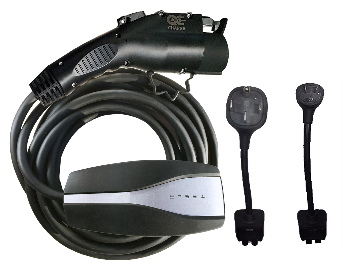
Jesla Jr™ - The 32 amp J1772 Portable Charging Solution!
JESLA JR™ is a J1772 charging unit and cable (about 16 feet in length) that charges up to 500% faster the original charging cable that came with your Electric Vehicle (EV). JESLA JR™ is safe to use on all voltages, 100 to 264 volts. JESLA JR™ is shipped with: Two FREE adapters: Adapter P and...
 qccharge.com
He could probably help with the wire diagram.
Upvote
0
FlatSix911
Porsche 918 Hybrid
Good analyis... thanks for sharing.Okay. Melted connector. This is down my alley.
So, power dissipation goes by I^2*R. Double the current with the same resistance, wherever that resistance may be, and the power squares.
And.. there's fusing. A Mobile Connector hooked up to a NEMA14-50. There's a breaker backing up the NEMA14-50 in the breaker box. In fact, that breaker, in US/Canadian style, will have two physical breakers, each one on a hot, rigged so if one does too much current but the other doesn't, the one that trips drags the other one with it. Hence the term, "ganged". There's no fuse on the neutral/ground at the breaker box.
- Let's talk about resistances. Wire's got resistance. Any kind of connector has resistance on the contacts. Usually, 10's of milliohms. Where are the connectors in all of this:
- NEMA14-50 blades that carry the two hots.
- Adapter in the TMC.
- Pins in the Tesla charging port connector. Three high-power ones; I think the big ones are 120VAC to neutral, each, and 240 across the pins. I'm not sure about the bottom pin, but that's either ground or neutral. The little guys are communications protocol follies.
- Then, the pins connect to wires on the back side of the connector block. I haven't had one of these apart. Nice, thick, wires, I'm sure. Lockwashers and bolts? Or are they soldered? In any case, the other ends of those wires are connected to, probably, lugs on the circuit boards with flat washers and bolts galore.
Further, the car itself has current detectors. On the hots. So, if too much current gets drawn things get turned off in a hurry. Safety first.
So, what happened?
Since the car/Tesla connectors melted, the heat must have been in and around the pins. It wouldn't have been at the NEMA14-50. It wouldn't have been at the pagoda or wherever it is that the cables that connect the power to the internal electric boards are connected - that far away, the boards down there would have fried. And those boards didn't get replaced.
So, either there was Too Much Current or Too Much Resistance. Somewhere.
OK. So, 50A breakers did not pop. But! The Mobile Connector only charges at 32A. But.. that's the maximum load the car will put across the two hot pins. So, suppose we had some kind of a short between, say, between Hot #1 and ground. If we got 50A breaker, then the maximum current we could have on this short would be 50-32 = 18A to, say, ground. At 120VAC (since we're talking a single hot here). That would be a power level of 2.16 kW; and, yeah, the heat from that on that connector would likely melt things.
But that assumes a short circuit in and around the power connector. Hmm.
Next thought: resistance. Well.. there's a couple of possibilities in this direction.
First, any of you who have looked will notice that the connectors inside the Tesla connectors are colored silver. That's not an accident - they are extremely like to be silver. Silver having the highest conduction/lowest resistance of any metal standing around. But, silver has a problem: It oxidizes. And silver tarnish isn't quite as good a conductor as the naked stuff, no surprise there. Most of the junk I work with where we want long-term reliability gets gold plating, since gold doesn't corrode particularly. Doesn't conduct as well, but you takes your lumps as you gets them.
There's a couple of tricks with high power connectors:
But, so long as we're talking about silver contacts: I have to ask the OP. Got a lot of odd vapors in your garage? If you leave a silver spoon on top of a surface, does it get funny colored after a week? Do you live downstream of an air polluter, and yellow skies are in your typical forecast? Doubt all this, but gotta ask.
- Wiping action. If there's metal, spring-loaded ridges in the connectors designed to scrape along the sides of the pins, and the pins are thick enough, it can wipe the corrosion off.
- Arcing. One sees this on relay contacts. As the contacts open/close with a high enough voltage, a little arcing occurs which tends to blow corrosion products into vapor. It also pits the connector (or switch) where this occurs, but this is why connector/relay engineers are paid the big bucks. (This is also the reason that old city-power switches die after a dozen years or so of use: After N number of cycles of arcing, the switch contacts become junk.)
And, then there's this screwy idea I've got. Um. So, I've never seen the guts of a Tesla connector, the version in the car, anyway. But a typical way of getting a wire onto one of those pins would be for the inside, car-end of the pin to have a cup, large enough to put a nice, thick wire into. Tightly.
There's two ways I can think of for that cup and wire to become connected:
And this is where things can go wrong. I'd like to think that any solder or crimp job would be highly automated; i.e., very unlikely for a mistake to be made. But say that the construction of that block-of-black-plastic-with-pins-and-wires was farmed out to some supplier, and said supplier was doing hand-crimping or hand-soldering. And that's where things can get weird.
- Crimp it. That's, like, really common for bog-standard automotive grade connections. But this sucker is seriously high current.
- If one wants really low resistance on a cup-to-wire connection, one solders it.
With a crimp job, let the die get damaged, or badly worn, and nobody notices, and there might be a slew of poor connections out there. Or if some hand-doing-it type has a Bad Day, or it's some New Guy who didn't quite pick up on the procedure..
With a solder job, it's all about cold and fractured solder joints. And those can be hard for the uninitiated to spot. With a proper solder job, the metals that one is soldering together are made hot enough to melt solder; then the solder is applied. The solder will melt and wick into the joint. But that doesn't stop there. Solder actually dissolves into both metals. One then backs off and lets the whole business cool. When finished, there's supposed to be a smooth transition from <connector-on-one-side-with-no-solder> to <connector-on-one-side-with-increasing-solder> to <solder only> to <solder-decreasing-on-the-other-connector> to <pure metal of the other connector>. No air gaps, thank you.
When done right, everything is shiny and smooth. And the joint, no kidding, is stronger than the wires.
So, in the terms of What Could Possibly Go Wrong?
- Cold solder joint: Heat the cup and the wire, but maybe not enough. The solder might wick onto the cup, but not the wire, or vice versa. Whatever it got wicked onto will look nice and shiny when cool, but the edges of the fillets will be abrupt. There might be incidental contact but, where stuff wasn't soldered, corrosion (just the O2 in air, mind you) will slowly increase over time, raising the resistance.
- Fractured joint. Some solders go from liquid to solder Just Like That. A lot more of them have a plastic phase. If one is in the plastic phase and the joint/wire gets moved (manufacturing process line moving too fast, maybe?), the plastic solder can fracture, leaving a microscopic crack interior to the solder. Yeah, corrosion, time, expansion and contraction, and, eventually, high resistance.
So: Does anybody have an idea what the connector in a Tesla, on the wiring side, actually looks like?
- The original failure could be, well, original.
- The second failure.. I'm a-wondering if the techie at the Service Center got given a connector body without wires attached. Crimp job or solder job, but then was told to Just Do The Job. IF that was the case, the list of possibilities just get Right Up There. It takes training and kill to Do It Right; not that everybody who does a bit of soldering touch-up needs to be God, but there are Reasons there are NASA-certified soldering technicians who get qualified and tested every three months, and get paid princely salaries for their work. (Think: Voyager spacecraft, still chugging after all those years with not a repair person in sight.) Some well-meaning gonzo at an SC isn't in the same category.
Upvote
0
Similar threads
- Replies
- 19
- Views
- 687
- Replies
- 1
- Views
- 384
- Replies
- 3
- Views
- 299
- Replies
- 5
- Views
- 1K