Welcome to Tesla Motors Club
Discuss Tesla's Model S, Model 3, Model X, Model Y, Cybertruck, Roadster and More.
Register

NEMA 14-50 Plug Meltdown / Near Fire

This site may earn commission on affiliate links.
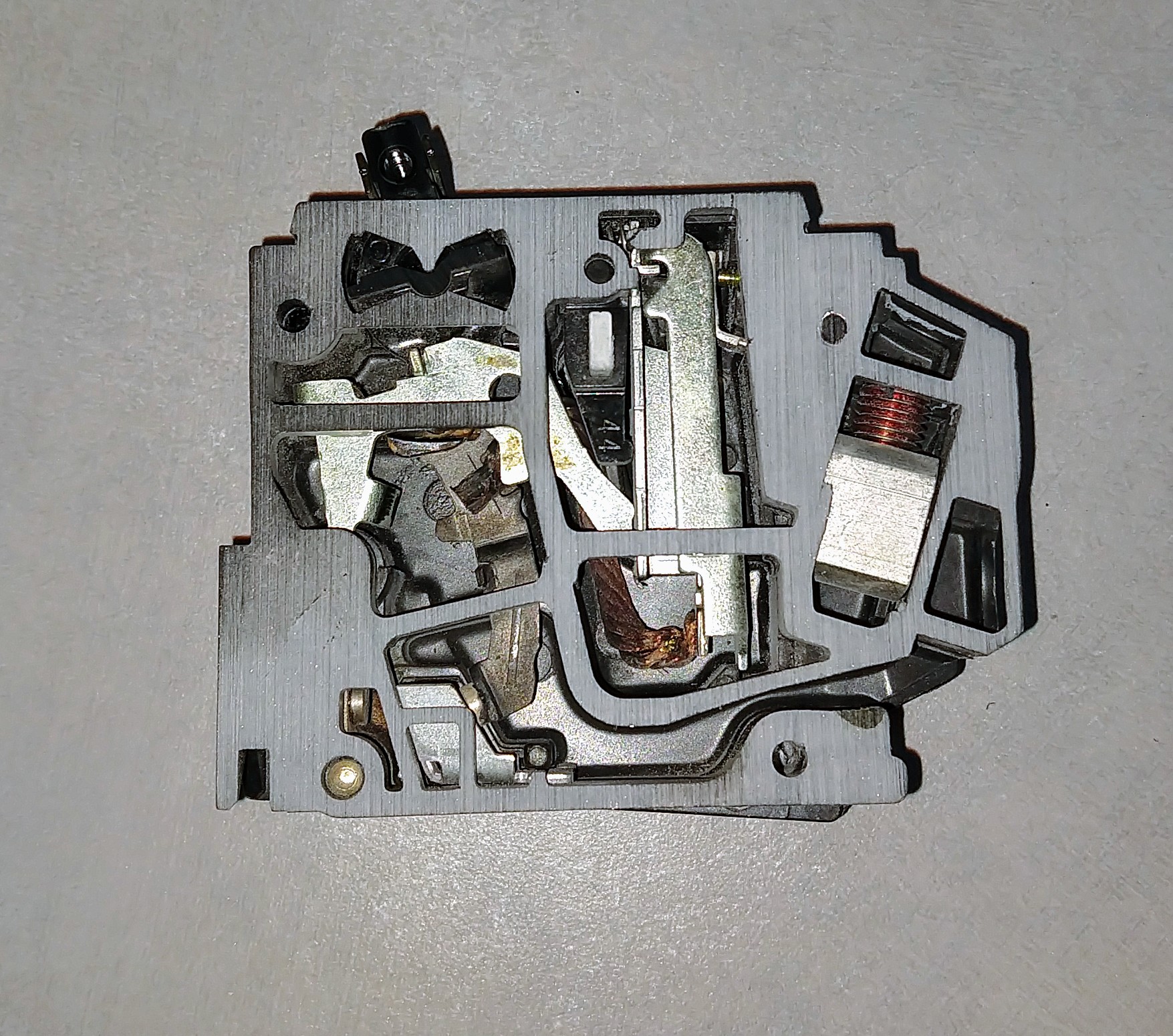
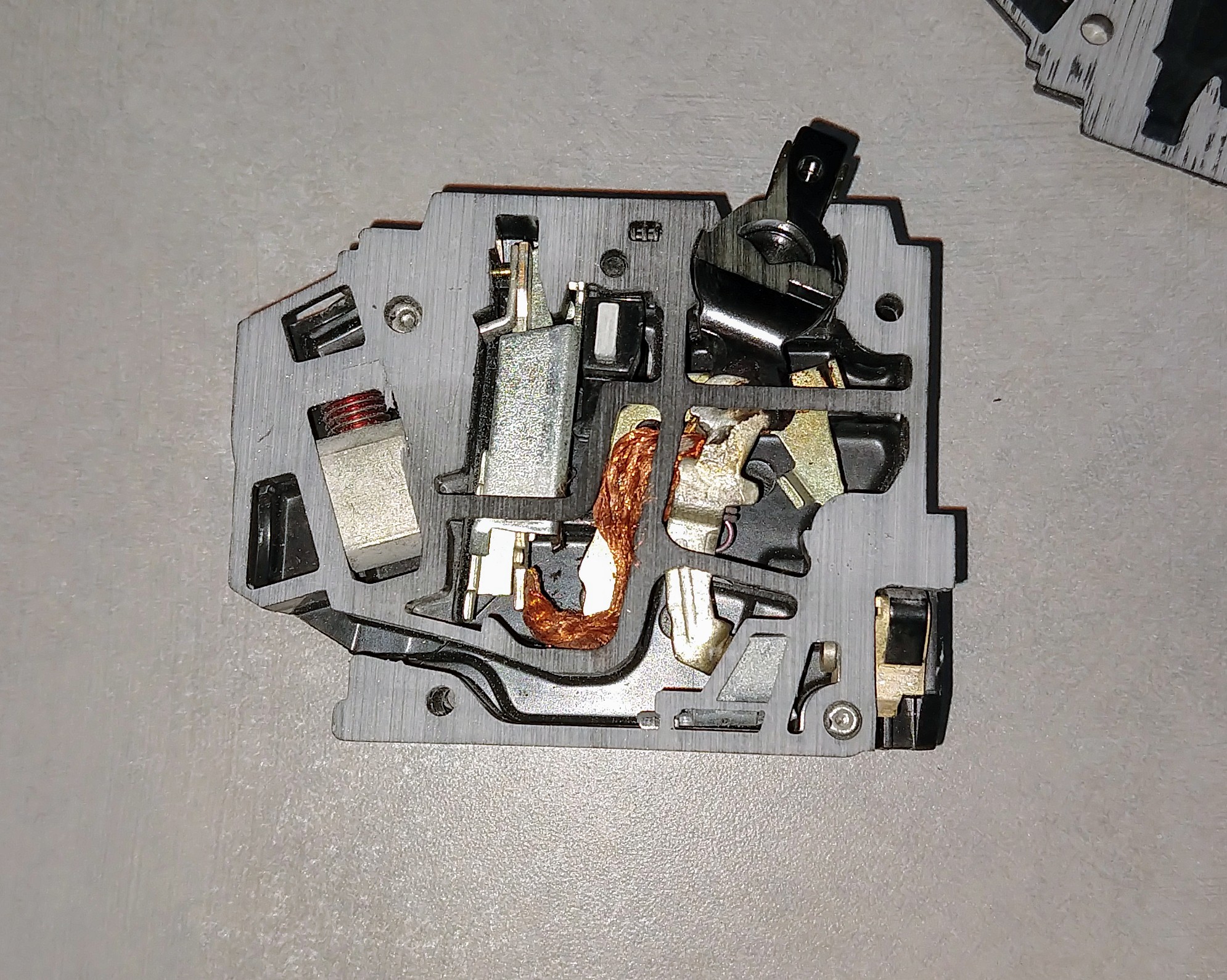
If that's true it sucks at it's own algorithm. My circuit breaker melted down before it tripped because of a chattering contact inside the breaker. The Tesla just kept pulling until it melted completely.


100% agree...I test breakers at work to ensure they still trip so I will put them under a 120% load until they trip. Sometimes they don't trip until I hit 140%+ for 5 minutes or so. Temperature has a lot to do with it. If it's cold where the breaker is, but the wires are wrapped in insulation, it's possible that the wire could fail before the breaker trips.

A cheapish FLIR is a good thing for a homeowner to have. $200 for your smartphone. Probably cheaper elsewhere.

flirone-gen3-consumer.png


FLIR ONE Gen 3 Thermal Camera for Smart Phones | FLIR Systems

Yep, this reminds me it is about time for my not so regular check of breaker temps and outlet temps...with my FLIR One. :)
 
Tesla supposedly has advanced algorithms that continuously monitor for voltage drops during the charge cycle. Somehow these algorithms must have failed in order for the outlet to be smoking. The only thing that saved you was the circuit breaker.


Not necessarily, if you want to call a simple 'droop check' an 'advanced algorithm' - that is up to you. But a very stout wiring job will not be detected if it is ONLY the 14-50 P that is heating (and getting so hot that it melts the female receptacle).

Reason? There is not enough 'droop' to kick in the power reduction program. It can't be too sensitive otherwise almost everybody's installation will enable it unnecessarily.

ON a humorous note, one of new LEADS - Qualifying buildings near me had 3 - 115 volt receptacles near 3 'green' parking spots for ev's. I plugged my Roadster in - and the car errored; it accused me of using an extension cord!. Too much 'Saturday Helper' #12 romex between the main building and the parking lot!
 
image.jpeg image.jpeg
View attachment 416954 View attachment 416958 View attachment 416959

My main house breaker tripped tonight. Upon investigating, I saw black smoke curling up my garage wall and smelled burning plastic, from where my 14-50 plug is located. Turns out my electrician had installed the plug with a loose black conductor, causing the outlet and plug to meltdown. At this point I am much more relieved than upset because I was able to stop what could have been a disaster. I will be double-checking every connection myself going forward in the install of a HPWC to replace the 14-50! If you smell burning plastic, investigate!
Don't know if this helps. I just had a electrician install the 240 volt Nema 14-50. It's charging with no issues. What he told me is its important to know the name brand of the breaker panel which is on inside cover of the panel. The fuse breakers are very specific as to what type double pole fuse breaker is installed.
 
Just wanted to give thanks to this thread. I installed a 14-50 circuit on my own and used a leviton receptacle with the screw clamps. I opened up the box after reading this thread, and with the exception of the ground wire, all the screws were pretty loose. More than 1 full turn to get them tight again. It's been 15 months since install. I did notice that my voltage was lower than when it was first installed. The app and car used to read over 240V. Lately it was around 236V. Now that the screws are tightened, it's back up to 241V.

I'll check it periodically now to make sure things are still tight. And may consider replacing the receptacle at some point.
Makes me glad as OP to have posted, in that it might have saved you and others some trouble or grief! Happy and safe Tesla-ing!!
 
Yeah, on the install I helped with a couple days ago I was annoyed at how nearly impossible it is to see the wires you are terminating in the Wall Connector. I actually emailed Tesla charging support about this and chastised them for not having a strip gauge on the unit (like every breaker does) or even specs on the proper strip length in the manual. Even more importantly they need to engineer the product so you can visually see if you are catching insulation in the lugs. I was barely able to shove my face up in there and verify this.

I just installed my wall charger on Monday after my electrician ran the 60A line from my panel to my garage (the WC had not come in time for the wire install). This thread has me terrified that I might have screwed it up, because I struggled quite a bit with it. The conduit mounted to the wall did not allow for any wiggle room in the mounting position of the wall charger bracket, and since the terminals on the inside of the WC are so close to the entry point, the wires are short, leaving VERY little flex in a 7 strand, 6g wire. Add to that the fact that I was pretty much working blind up in there, as you say, and I struggled quite a bit. The first time I shoved the wires up in there and bent the wire straight so they would fully insert in the terminal, for some reason I didn't catch the clamp because when I screwed it back down, there was no resistance. I unscrewed it and withdrew the wire so the clamp could open to the other side of the wire, but the only way I could tell if I got it right was when I screwed it back down and felt resistance.

I'm sure I got it all in there correctly and it's charging perfectly, but now I'm paranoid that it wasn't perfect. Trouble is, with the WC designed as it is, I could easily see a trained electrician messing it up too.
 
Reason? There is not enough 'droop' to kick in the power reduction program. It can't be too sensitive otherwise almost everybody's installation will enable it unnecessarily.

ON a humorous note, one of new LEADS - Qualifying buildings near me had 3 - 115 volt receptacles near 3 'green' parking spots for ev's. I plugged my Roadster in - and the car errored; it accused me of using an extension cord!. Too much 'Saturday Helper' #12 romex between the main building and the parking lot!

Yikes! What kind of voltage was it seeing that it rejected charging altogether?

I was at a campground a few weeks ago using a TT-30 adapter; that maxes at 120V/30amps.
I rate-limited the Model 3 to 30amp draw, and when I plugged in, I saw the voltage was between 99-100V. Definitely a long run from the distribution site - such is the nature of a campground. It wasn't much better than using a "stout" 120V/15a circuit, but the TT-30 circuit was included in my campsite rental.

At home, I have an HPWC and usually charge at about 237V/48A. I figure that's pretty robust - not sure I could get much better.

On a TT-30 (30a circuit) you should be limiting current to 24 amps! 80% of 30. Your voltage drop issues may have been in part due to you over drawing on the circuit (but yeah, probably mostly due to really long wires improperly sized, or maybe loose connections too).

I usually get around 245v at 48a at home (I am close to the substation and my transformer). Very solid charging speed!!!
 
  • Helpful
  • Like
Reactions: GSP and dbldwn02
I was at a campground a few weeks ago using a TT-30 adapter; that maxes at 120V/30amps.
I rate-limited the Model 3 to 30amp draw,
Oh, no!
On a TT-30 (30a circuit) you should be limiting current to 24 amps! 80% of 30.
Yeah, this is vitally important that people follow that 80% rule. This is why I am really glad that EVSEAdapters finally was able to start making real-ish adapters that fit directly to the UMC and dictate the current limit. It's a bit risky for people who don't know this stuff well enough to use adapter of a 30 amp outlet to a 50 amp outlet type and think that they can run constant 30A from a 30A circuit.
 
On a TT-30 (30a circuit) you should be limiting current to 24 amps! 80% of 30. Your voltage drop issues may have been in part due to you over drawing on the circuit (but yeah, probably mostly due to really long wires improperly sized, or maybe loose connections too).

I usually get around 245v at 48a at home (I am close to the substation and my transformer). Very solid charging speed!!!

Sorry, it was 24. That's correct and what I did (my bright yellow sticker on the TT-30 says so) - sorry that's what happens when I don't sleep.
 
  • Informative
  • Love
Reactions: GSP and eprosenx
5B3F4675-C1A5-487F-8DDA-D63047BA1EF9.jpeg
Oh, no!

Yeah, this is vitally important that people follow that 80% rule. This is why I am really glad that EVSEAdapters finally was able to start making real-ish adapters that fit directly to the UMC and dictate the current limit. It's a bit risky for people who don't know this stuff well enough to use adapter of a 30 amp outlet to a 50 amp outlet type and think that they can run constant 30A from a 30A circuit.

No, no, total mistype on my part... I did set it to 24amps. Followed the directions :)
 
View attachment 416954 View attachment 416958 View attachment 416959

My main house breaker tripped tonight. Upon investigating, I saw black smoke curling up my garage wall and smelled burning plastic, from where my 14-50 plug is located. Turns out my electrician had installed the plug with a loose black conductor, causing the outlet and plug to meltdown. At this point I am much more relieved than upset because I was able to stop what could have been a disaster. I will be double-checking every connection myself going forward in the install of a HPWC to replace the 14-50! If you smell burning plastic, investigate!

Does the plastic face of your 14-15 plug (the side the faces the UMC) have a black or grey color (before the melting, in case it is changed now)? In your first photo, this would be the side that is facing down and resting on the surface.
 
  • Helpful
Reactions: eprosenx
This is a serious issue. Contact Tesla immediately for assistance. You need that unit (or its cord or the charge port on your car) replaced.

Hot is *not* ok.

I have had a similar experience at some of the early model superchargers. I have noticed that the "handles" on the newer ones seem cushioned and only get warm.

I did mention it to the mobile tech who met me in a shopping center to replace my passenger side airbag. He said that Tesla has replacement cable/ connectors for the wall units, with 24 ft cable. My original cable is 18 ft. I have heard that the longer the cable, the warmer it gets. I know this is true for three-wire AC extension cords. I do not need more than 12 feet. I do not know if they can be shortened.
 
ON a humorous note, one of new LEADS - Qualifying buildings near me had 3 - 115 volt receptacles near 3 'green' parking spots for ev's. I plugged my Roadster in - and the car errored; it accused me of using an extension cord!. Too much 'Saturday Helper' #12 romex between the main building and the parking lot!

But if it was done by a licensed electrician, "It should be safe and correct 100% of the time", right? :p. At least that's what a lot of people here are saying.
 
  • Like
Reactions: Jaywlker
But if it was done by a licensed electrician, "It should be safe and correct 100% of the time", right? :p. At least that's what a lot of people here are saying.

I think it’s incorrect to place the blame for this particular mistake on the last person in the long chain that produced this particular building and ultimately installed this circuit. I also agree that just because you think someone who calls themselves an Electrician, or really any profession knows all aspects of what they’re charged with performing, be they state licensed or not.

Many people were involved with the planning and execution of the project and lest we forget, all are capable of making mistakes anywhere along that chain. If on the E- sheet in the building drawings it called for #12 conductors, I’m sure that’s what were installed. Also involved is that “jobs” are bid and awarded by the lowest bid, there’s that to consider also. When a mistake is uncovered the “Electrical” sub contractor (in this case) has to jump through hoops to get an approved a change order, this may simply have been missed in the shuffle to complete the project and for the general contractor and “subs” to get paid...
 
  • Like
Reactions: dbldwn02
I think it’s incorrect to place the blame for this particular mistake on the last person in the long chain that produced this particular building and ultimately installed this circuit. I also agree that just because you think someone who calls themselves an Electrician, or really any profession knows all aspects of what they’re charged with performing, be they state licensed or not.

Many people were involved with the planning and execution of the project and lest we forget, all are capable of making mistakes anywhere along that chain. If on the E- sheet in the building drawings it called for #12 conductors, I’m sure that’s what were installed. Also involved is that “jobs” are bid and awarded by the lowest bid, there’s that to consider also. When a mistake is uncovered the “Electrical” sub contractor (in this case) has to jump through hoops to get an approved a change order, this may simply have been missed in the shuffle to complete the project and for the general contractor and “subs” to get paid...

I 100% agree with everything you said. It's just a lot of people here are under the false assumption that only licensed electricians can prevent you from burning your house down.

Being an electrician in the military (not licensed by any state), I would call B.S. on a 12AWG run if the drawings showed it. Showing pictures of what that can cause, makes people up the chain think twice. Twice as much money now vs. 10 times as much later when you have to rip it all up.
 
Yikes! What kind of voltage was it seeing that it rejected charging altogether?

I was at a campground a few weeks ago using a TT-30 adapter; that maxes at 120V/30amps.
I rate-limited the Model 3 to 30amp draw, and when I plugged in, I saw the voltage was between 99-100V. Definitely a long run from the distribution site - such is the nature of a campground. It wasn't much better than using a "stout" 120V/15a circuit, but the TT-30 circuit was included in my campsite rental.

At home, I have an HPWC and usually charge at about 237V/48A. I figure that's pretty robust - not sure I could get much better.


As far as my Roadster was concerned - the thing only checks droop when charging with the 115 volt cord that comes with the car. There were (at this LEADS qualifying Art Gallery) 3 nicely painted EV spots (due to the size of the Gallery), of which 1 just never worked period, and the other 2 worked - of course few architects or electricians ever take into consideration percentage voltage drop, even though the NEC requires the next larger wire size when the first outlet is over 100' distant. I knew it was a 20 ampere circuit, rather than an 15 because the receptacles were 5-20 ground faults. Of course, if they had run 15 ampere breakered circuits with 5-15's at the car, it would have been perfectly legal with the same #12 AWG wires and the Roadster would respond in the same way. Its not a big deal since in this case there is very little heating.

My main point about commenting here - is that in my opinion the majority of the blame goes to that initially poorly designed Nema 14-50P attachment plug, which as I say got unreasonably hot even at the Tesla Service center. As mentioned Tesla eventually did 3 separate things to ameliorate the trouble, but I'm sure across the US and Canada there have been multiple close calls - blamed on electricians and inspectors - when they are not to blame usually. Of course - Leviton's chintzy junk gets honorable mention here as far as contributing to the heat issue.

Now myself, I have a good quality EAGLE Nema 14-50 receptacle in a metal extender box far away( 2 ") from the garage wood framing, which nowadays I mostly use it for a portable 32 ampere J1772 charger cord, or my home made snow blower - which typically draws 14 amperes and maybe 35 amperes for several seconds in severe weather. Of course, being unbelievably cold at the time helps.
 
  • Like
Reactions: Jaywlker
Since my 2nd UMC died I always charge at ~20A unless I need more. 20A is more than enough ~95% of the time. The heat generated from current is squared so 40A generates 4x as much heat as 20A.

I connect the UMC Gen 2 to 10-30R dryer receptacle and limit the current at 25A. Everything seems to be OK. The hottest part is the cable of the the UMC. Does anybody know what is the size of the conductor inside the cable (2 hot wires)? Are they 8, 10 or 12 AWG? Thanks
 
On a 30 amp circuit you should be at a maximum of 24 amps. (80% of 30).
A 30 amp circuit is installed with 10 gauge wire.

A Gen 2 is limited to 32 amps and should be on a 40 amp circuit for the full current.
A 40 amp circuit would probably be wired with 8 gauge wire. I've never seen one.
Next up is a 50 amp circuit which is wired with 6 gauge wire.
 
  • Informative
Reactions: Rocky_H
On a 30 amp circuit you should be at a maximum of 24 amps. (80% of 30).
A 30 amp circuit is installed with 10 gauge wire.

A Gen 2 is limited to 32 amps and should be on a 40 amp circuit for the full current.
A 40 amp circuit would probably be wired with 8 gauge wire. I've never seen one.
Next up is a 50 amp circuit which is wired with 6 gauge wire.

40A circuits with 14-50 outlets are common for electric ranges.

You can use 8 AWG wire if it's THHN in conduit for up to 55A, but I understand most electricians will upsize to 6AWG for added safety.
 
  • Informative
Reactions: eprosenx