Welcome to Tesla Motors Club
Discuss Tesla's Model S, Model 3, Model X, Model Y, Cybertruck, Roadster and More.
Register

Newer P90DL makes 662 hp at the battery!!!

This site may earn commission on affiliate links.
Status
Not open for further replies.
Edmunds list the front final drive ratio as 9.34. Since this is a taller ratio than the rear, it would be better to send as much hp to the rear as possible because you get more torque per hp.

Actually this is not true. It also means that at the same vehicle speed, the front motor will be turning less RPMS than the rear motor.. If both motors are getting 200KW for instance, the front motor will produce more torque than the rear because the front motor's RPMS are less than the rear motors at the same vehicle speed. By the time that makes it to the front and rear wheels, both front and rear wheels are producing the same torque.

This also assumes equal drivetrain losses from motor through diff to wheel axles, but 9.34 will have lower drive train losses than 9.73 so in reality, equal power applied from both front and rear axles will result in just a little more torque at the front wheels as the front diff is more efficient.
 
Last edited:
Actually this is not true. It also means that at the same vehicle speed, the front motor will be turning less RPMS than the rear motor.. If both motors are getting 200KW for instance, the front motor will produce more torque than the rear because the front motor's RPMS are less than the rear motors at the same vehicle speed. By the time that makes it to the front and rear wheels, both front and rear wheels are producing the same torque.

This also assumes equal drivetrain losses from motor through diff to wheel axles, but 9.34 will have lower drive train losses than 9.73 so in reality, equal power applied from both front and rear axles will result in just a little more torque at the front wheels as the front diff is more efficient.

Yes, of course. If the front and rear wheels are both rotating at the same speed and the same horsepower is going to them they must both be generating the same torque. But as it turns out, it doesn't really matter. Most of the power is being generated by the rear motor and there's not much difference between 9.34 and 9.73, so using 9.73 to get the combined torque at the motors is still pretty close.

Will the 9.34 have less losses even with the required increased torque from the motor? There's probably additional losses in the u-joints at the front axle also. But I think we can ignore these as the 5% I used for the gearbox was a guess anyway. I think this calculated torque is accurate enough to see how it is changing through the 1/4.
 
Last edited:
@sorka, when you said that the 9.34 will have lower drive train losses, were you talking about the apparent loss of horsepower on an inertial dyno with shorter gearing? Or is there more power dissipation in the differential itself if it has shorter gearing? I would think that extra input shaft torque required with taller gearing would put more load on gear tooth faces and more load on bearings. This would decrease oil film thickness and increase friction. I suppose the larger ring gear spinning through the oil might cause more viscous losses, but these have to be small.
 
@sorka, when you said that the 9.34 will have lower drive train losses, were you talking about the apparent loss of horsepower on an inertial dyno with shorter gearing? Or is there more power dissipation in the differential itself if it has shorter gearing? I would think that extra input shaft torque required with taller gearing would put more load on gear tooth faces and more load on bearings. This would decrease oil film thickness and increase friction. I suppose the larger ring gear spinning through the oil might cause more viscous losses, but these have to be small.

Most of the loss measurement is due to inertial loss due as the larger reduction requires a larger gear. So a static dyno run that measures power by applying the PAU to absorb a constant amount of energy to keep the speed constant should not see a loss from one ratio to another. An acceleration run will be a different story as the extra mass being accelerated will take take more energy.

Also, the larger gear in the larger reduction will have a lot more surface area and teeth fighting viscosity, but it will also be spinning slower, so I honestly don't know how much of an affect that has.

The reason we dyno cars in the gear that is 1:1 is that it has the least amount of mass spinning in the transmission. A car that loses 15% in 4th gear will lose closer to 30% in first gear.
 
Last edited:
sorta, thanks. That's what I thought. The torques I calculated are more like static dyno numbers. It's all of the torque available from the motors. Not all of it will be available to accelerate the car. Some of it will have to spin-up the wheels, shafts and motor rotor. But it's more representative of the motor capability, like a motor dyno rather than a chassis dyno. So in this case I think the losses would be about the same for the two diffs.
 
@sorka, I think there might be another reason to make hp preferentially with the rear motor. As you pointed out, for the same hp the taller geared front motor has to make more torque. More torque would require more current, and we have a limited current budget of 1500 amps.
Sorry about misspelling your identity on my previous post.
 
@sorka, when you said that the 9.34 will have lower drive train losses, were you talking about the apparent loss of horsepower on an inertial dyno with shorter gearing? Or is there more power dissipation in the differential itself if it has shorter gearing? I would think that extra input shaft torque required with taller gearing would put more load on gear tooth faces and more load on bearings. This would decrease oil film thickness and increase friction. I suppose the larger ring gear spinning through the oil might cause more viscous losses, but these have to be small.
The higher the ratio, the higher the final drive torque is produced. That would place more torque to the rear wheels. This concept can be demonstrated via torque wrench. Applying 50lb of force on a 1ft torque wrench. Would yield 50lbft of torque. 50lb of force applied to a two ft torque wrench would yield 100 lbft of torque. That is a 2:1 ratio.

John
Yeah, that was the mistake I made assuming the different final drive ratios would produce different torques. But because the front and rear tires are forced to rotate at the same rpm, you get the same torque at the wheels if they receive the same horsepower, regardless the final drive ratio. The motor with the taller ratio spins at a lower rpm thus has to generate more torque so that the final torque at the wheels is the same at the front and rear. But you do pay for that taller gear on the front in the form of higher current draw.
 
Last edited:
Most of the loss measurement is due to inertial loss due as the larger reduction requires a larger gear.

That is incorrect. The larger gear has more inertia (proportional to mass times R squared) but it is also being subjected to a larger torque. The inertial load seen by the motor is proportional to 1/(N squared) where N is equal to the gear ratio. This is because the larger gear is being subjected to a larger torque *and* a smaller angular acceleration. As a result the larger gear has essentially zero effect on the acceleration due to its larger diameter. However, the larger gear does affect the inertial load that the motor sees from the remainder of output shaft load.
 
Inertia Resistance (IR):


image004.gif


where:

IR = inertia resistance [N]

m = car mass + equivalent mass of rotating parts [kg]

a = car acceleration [m/s2], (from 0 to 100 km/h in: 6 s (4.63 m/s2), 18 s (1.543 m/s2))

mcar = car mass [kg]

meq = equivalent mass of rotating parts [kg]

= [ Iw (1/rw)2 + Ip hf (if /rw)2 + Ie ht (if ig / rw)2]

where:

Iw = polar moment of inertia of wheels and axles ≈ 2.7 [kg m2]

Ip = polar moment of inertia of propeller shaft ≈ 0.05 [kg m2]

Ie = polar moment of inertia of engine ≈ 0.2 [kg/m2] + polar moment of inertia of flywheel and clutch ≈ 0.5 [kg m2]

hf = mechanical efficiency of final drive


ht = mechanical efficiency of transmission system (hg x hf)

ig = gearbox reduction ratio [ig1 or ig2 or ………….]

if = final drive reduction ratio

rw = tire radius [m]

This give a method of calculating and equivalent mass from rotating parts. All of the polar moments that are on the input side of the differential get multiplied by if, which is the final drive ratio. So the larger the final drive ratio is the larger their equivalent mass. The total mass of the car is the mass of the car plus the equivalent mass. As you increase the final drive ratio, the rotating parts equivalent mass become a larger fraction of the total mass of the car so takes a larger faction of the available torque.

But this diverted torque isn't lost to use because we can recover some of the rotational kinetic energy during regen.
 
Last edited:
@sorka, I think there might be another reason to make hp preferentially with the rear motor. As you pointed out, for the same hp the taller geared front motor has to make more torque. More torque would require more current, and we have a limited current budget of 1500 amps.
Sorry about misspelling your identity on my previous post.

The torque the motor makes at any particular RPM is based on the KW(power) fed into, not the current.
 
That is incorrect. The larger gear has more inertia (proportional to mass times R squared) but it is also being subjected to a larger torque. The inertial load seen by the motor is proportional to 1/(N squared) where N is equal to the gear ratio. This is because the larger gear is being subjected to a larger torque *and* a smaller angular acceleration. As a result the larger gear has essentially zero effect on the acceleration due to its larger diameter. However, the larger gear does affect the inertial load that the motor sees from the remainder of output shaft load.

Right, so is that last sentence your explanation as to why the shorter gears have more drivetrain loss?
 
The torque the motor makes at any particular RPM is based on the KW(power) fed into, not the current.
For a given KW in you can have different combinations of rpm and torque. Lower rpm means torque must go up. Higher rpm, torque must go down to maintain the power. For a given product of rpm and torque the motor requires a certain current. Now if your start lowering the rpm the torque will have to start going up and the motor will draw more current to generate this increased torque. The lower the rpm of the motor the lower the frequency of the inverter. When the frequency of the inverter drops the voltage to the motor must also be lowered to maintain a constant volts/hz relationship. This more or less keeps the torque the same. Now to get the higher torque the slip between the rotor speed and the speed of the rotating magnetic field must increase. Increased slip leads to more stator current. The voltage has gone down and the current has gone up to maintain the same electrical power while the rpms have gone down and the torque has gone up to maintain the same mechanical power.
 
For a given product of rpm and torque the motor requires a certain current. Now if your start lowering the rpm the torque will have to start going up and the motor will draw more current to generate this increased torque.

That's completely untrue. Lowering RPM at the same power input level will of course increase torque but that will not mean current from the battery goes up.
 
Last edited:
That's completely untrue. Lowering RPM at the same power input level will of course increase torque but that will not mean current from the battery goes up.

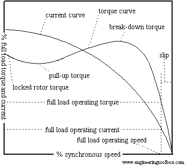
Basically current is torque. If the inverter is operating at some frequency and there is no load on the motor the rotor's rpm will almost match the rpm of the rotating magnetic field from the motor stator and very little current will be required. Now as you place a torque load on the rotor it will slow down and its rpm will no longer match the speed of the rotating magnetic field. This is called slip. The greater the load you apply the more slip you need. Increased slip causes more current draw.

What I've described is depicted on this plot of torque and current vs slip. Here slip is labelled % synchronous speed. You start in the lower right corner of the plot where there's no load and the rotor is spinning at close to synchronous speed. Now as slip is increased, moving to the left on the plot, both torque and current increase. You can't get more torque without more current. Now the inverter also lowers the voltage to the motor to keep power constant. But the increased slip lowers the efficiency of the motor so more power would have to be drawn from the battery.

 
Last edited:
In addition to lower efficiency of the motor, to achieve the lower voltage to the motor the duty cycle of the inverter's pwm will have to decrease and the current pulses will have to increase to maintain the same average current from the battery. Those higher current pulses will cause more i squared r losses across the battery's internal resistance, unless there's a smoothing filter between the inverter and battery. All the following power electronics will also dissipate more power due to the increased current. All these losses will have to be made up by extracting more power from the battery than goes to the motor.
 
Last edited:

Basically current is torque. If the inverter is operating at some frequency and there is no load on the motor the rotor's rpm will almost match the rpm of the rotating magnetic field from the motor stator and very little current will be required. Now as you place a torque load on the rotor it will slow down and its rpm will no longer match the speed of the rotating magnetic field. This is called slip. The greater the load you apply the more slip you need. Increased slip causes more current draw.

What I've described is depicted on this plot of torque and current vs slip. Here slip is labelled % synchronous speed. You start in the lower right corner of the plot where there's no load and the rotor is spinning at close to synchronous speed. Now as slip is increased, moving to the left on the plot, both torque and current increase. You can't get more torque without more current. Now the inverter also lowers the voltage to the motor to keep power constant. But the increased slip lowers the efficiency of the motor so more power would have to be drawn from the battery.


We're completely missing each other. I'm talking about the current delivered the battery. The torque at a specific RPM is determined by the power coming from the battery, not the current. The inverter will do with that power what it needs to do it manage motor. The point is, power from the battery = power at the motor shaft minus conversion loss.
 
We're completely missing each other. I'm talking about the current delivered the battery. The torque at a specific RPM is determined by the power coming from the battery, not the current. The inverter will do with that power what it needs to do it manage motor. The point is, power from the battery = power at the motor shaft minus conversion loss.

Well at a fixed voltage the power is a function of the current, but I get your point if the power stays the same the current will also.

See my previous two posts, where I've 'suttly' shifted my argument to efficiency.
 
Last edited:
Status
Not open for further replies.