Ok need some help. I undertook the process of cleaning the entire PEM and motor air cooling system in the past couple of weeks. I was noticing increasing PEM temps while under moderate loads and it was obvious to me the system was loaded with debris. Temps are running high here in North Carolina so this was needed.
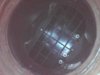
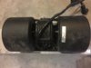
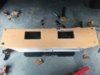
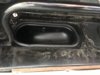
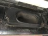
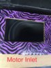
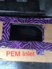
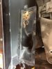
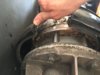
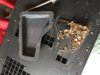
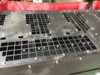
So, I removed the rear underbelly pan, removed single motor dual fan SPAL unit and blew it out with compressed air. No issues observed. Blew out ducts to PEM and motor, very little debris. Removed PEM. There was standing debris in the plastic duct that connects to the bottom of the PEM. Obviously I cleaned that. Started cleaning underside of PEM. Spent a good 45 minutes at least blowing out each heat sink with fins. Using compressed air, was amazed at the massive amounts of debris including leaves, pine needles, and fine dust coating all the heat sinks inside the PEM. Also removed the plastic cover on one of the heat sinks and again was amazed at the debris build up. Finally loosened the motor duct shroud and was able to slide it over to expose most of the top motor cooling fins. They were completely clogged with debris. Cleaned motor fins with vacuum and compressed air. Checked the blower motor connector on the PEM and no issues, so I didn’t take the approach of replacing female connector/pins.
So put everything together and went for a very slow drive. PEM temps quickly went over 40C and went as high as 46c, last blue bar. I never punched the throttle as I drove extremely conservatively. Ambient outside temp low 80s, at dusk, so no direct solar radiation on the car. Something is wrong.
Other data:
Motor temps stayed very low
Blower motor seems to run fine. It adjusts speeds normally as far as I can tell. Is it running at full RPM, not sure.
I do notice more air flow sound. Note sure if this is due to the thorough cleaning allowing more airflow through the PEM or could it be a sealing issue?
No errors. None, nada.
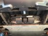
Assembly of duct to PEM wasn’t too difficult. Was able to line up the 4-5 small studs on side of PEM. And pull the duct towards the LH side of car. Clip snapped into place on the lateral side channel support.
Confirmed duct was still lined up with the studs.
Ideas? Thoughts? I am perplexed.
So, I removed the rear underbelly pan, removed single motor dual fan SPAL unit and blew it out with compressed air. No issues observed. Blew out ducts to PEM and motor, very little debris. Removed PEM. There was standing debris in the plastic duct that connects to the bottom of the PEM. Obviously I cleaned that. Started cleaning underside of PEM. Spent a good 45 minutes at least blowing out each heat sink with fins. Using compressed air, was amazed at the massive amounts of debris including leaves, pine needles, and fine dust coating all the heat sinks inside the PEM. Also removed the plastic cover on one of the heat sinks and again was amazed at the debris build up. Finally loosened the motor duct shroud and was able to slide it over to expose most of the top motor cooling fins. They were completely clogged with debris. Cleaned motor fins with vacuum and compressed air. Checked the blower motor connector on the PEM and no issues, so I didn’t take the approach of replacing female connector/pins.
So put everything together and went for a very slow drive. PEM temps quickly went over 40C and went as high as 46c, last blue bar. I never punched the throttle as I drove extremely conservatively. Ambient outside temp low 80s, at dusk, so no direct solar radiation on the car. Something is wrong.
Other data:
Motor temps stayed very low
Blower motor seems to run fine. It adjusts speeds normally as far as I can tell. Is it running at full RPM, not sure.
I do notice more air flow sound. Note sure if this is due to the thorough cleaning allowing more airflow through the PEM or could it be a sealing issue?
No errors. None, nada.
Assembly of duct to PEM wasn’t too difficult. Was able to line up the 4-5 small studs on side of PEM. And pull the duct towards the LH side of car. Clip snapped into place on the lateral side channel support.
Confirmed duct was still lined up with the studs.
Ideas? Thoughts? I am perplexed.
Attachments
-
 20B21024-5556-47C3-A2A9-ADE31C8A3E28.jpeg387.5 KB · Views: 206
 -
 A7257F11-A58F-4DA7-B6B9-520606975CD8.jpeg418.2 KB · Views: 144
 -
 CBE1469D-A4DF-496F-9EC7-048D6FA4F984.jpeg336.8 KB · Views: 153
 -
 A057FE1C-358E-4C18-A5DF-6714DA09EC15.jpeg591.8 KB · Views: 148
 -
 6FC8EEE7-140A-4D5A-AB8C-9D06127BA65B.jpeg436.6 KB · Views: 142
 -
 A1DA4CFD-BFAF-4DFD-ABC8-555ABEC97717.jpeg516.8 KB · Views: 156
 -
 792B7217-9273-4DDF-9968-85A075FF3405.jpeg390.1 KB · Views: 143