Welcome to Tesla Motors Club
Discuss Tesla's Model S, Model 3, Model X, Model Y, Cybertruck, Roadster and More.
Register

PWM signal to Condenser Fan Control Module - 1 out of 2 Fans going 100% speed

This site may earn commission on affiliate links.
Hi - Tesla Model S 85D, 2015.

I have a Condenser FAN (front left), going 100% speed as soon as i turn on the AC (or about 15 seconds after AC - ON, every time). The right one is going around 30% speed.

I just checked all my louvers (2 x front, Left and Right - and 2 x radiator, Left and Right), and everything is working as supposed to. (After changing my front left louver).

Outside temperature is about 70-75 F, which is not that hot IMO.

I have tried to read out some numbers from the PWM signal sent to each "Condenser Fan Control Module" after it kicks in.

Left CondensorFanControlModule:
Current:
Meassured 18.3A between control module and ground connection.
PWN signal: 99,9% - 13,44V – 0.8 Hz to 430 Hz (Jumping around, most values around 1-25 Hz - Which seems strange?!)

Right CondensorFanControlModule:

Current:
Meassured 2.7A between control module and ground connection
PWN Signal: 35.7% - 3.32V – 300.4 Hz (Very steady)

- Fuses and relays has been checked and swapped - No Change
- FAN speed should always be the same in each side - Of my knowledge

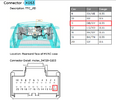
In the wiring diagram it says that the PWM signals connects to the thermal controller with 2 wires (FanPWM1 and FanPWN2)

Could it be:
- Bad thermal controller?
- Low pressure on the AC system/Low on refrigerant - The air is cold though (When i monitor the temperature of the refrigerant (ScanMyTesla) it goes pretty quick from 70 - 110 ish F)
- Something else?

I dont have a lot of knowledge about this PWM. However it seems like this signal should be sent from the Thermal Controller and that the signal sent to the Left Control Module is off in frequency (Hz)

If you got all the way to here, thanks alot :)

Have a great day
 
BTW:
- I also swapped the control modules - no change.
- Tried with a new Fan in each side - no change.

Left will still be going 100% and right is going around 30% speed

Think you already have the wiring diagrams but just in case.


fans.png


Seems to me that since you already checked the PWM signal and found 13V+ I think there is a short on the PWM wire. Could be an external short (PWM wire and another 12V+ are making contact) or an faulty thermal module.

If you disconnect wire X053 pin 11 from the thermal module and you still have 13V+ on pin 2 from the left fan module you have an external short.
When wire X053 pin 11 is disconnected and you measure directly on the thermal module and you measure 13V+ I think your thermal module is faulty.

Also attached location of the thermal module and connector.

Good luck.
 

Attachments

  • fans2.png
    fans2.png
    256 KB · Views: 142
Last edited:
  • Like
Reactions: HammerNow
Thanks alot for the inputs.. that will give me some hours of work to do :)..

wouldnt you think that it is the left fan doing the “wrong” thing?

Im pretty sure the PWM signal to the left fan isnt sending 12v+ all the time, but only when I turn on the AC (or 15-20 sec after AC - ON).. however its wierd with that frequency.. almost like meassuring the frequency on the 12v batt

once again thanks.. highly appreciated
 
One more thing,

Lets say that the 2 fans are supposed to always have the same speed, why have 2 PWM signals then?

If the right one is receiving the correct signal then (in theory) I could just Connect that same PWM signal to both fan control modules?
 
You may know that PWM (pulse-width modulation) regulates the speed of the fan with the 'duty-cycle' of the pulses. The longer the On pulses (meaning the shorter the Off pulses, since On + Off must = 100%), the higher the duty-cycle. The fan is just a coil, an inductor, and doesn't know from PWM. All it knows is how hot the signal is coming in, the duty-cycle. The higher the duty-cycle, the faster the fan.

In electronic circuits, more often than not, ground means activate. But the fan needs 12v to work. If you connect the 12v battery to the fan it will run at full speed since that's a 100% duty-cycle. As ground pulses are introduced the duty-cycle reduces and the fan slows down. If you have a defective or intermittent ground to frame it's possible that the duty-cycle will default to max.

You don't mention testing the input signal to the fan driver, but I'm going to make the reasonable assumption that it's normal, and possibly exactly the same as the other side, since the left fan is super-heat and right is super-cool, two stages in the 'getting rid of heat' process. You have swapped the fan drivers, presumably from one side to t'other, so that can't be it.

Which at this point would lead me to frame ground. Take it apart, even if it looks good, and put it back together with silicone grease. ("dielectric" grease at the auto parts store)
 
No luck after cleaning the frame ground in both sides, however the "right side" was really looking bad!

I gave the left "condenser fan control module" its own frame ground, because there was a "spare" (Could be for air suspension or something I don't have) just next to the original one.

To make sure that it was actually the correct wire leading to the left control module I meassured the current when the left fan turned on (meassured 18.9A)

LH - Front ground frame, Before:
LH-F before.jpg

LH - Front ground frame, After (Putting the ground connection to the "condenser fan control module" on its own frame ground):
LH-F-after.jpg

RH - Front ground frame, Before:
RH-F-Before.jpg

RH - Front ground frame, After:
RH-F-After.jpg

That leads me to the next step, which will probably be to get into that "Thermal Controller", looks like a pain, but hopefully i will get there within the next 2 days :)

If you know of any smart way to get there (To the X053 connector) without following the "Manual", please let me know. For now it looks like I have to disassemble alot of the dash and take out the Center screen. However I think it might be difficult to do all the meassurements with the center screen disconnected?

Once again thanks, this is invaluable.

Have a great day 👍
 
  • Informative
Reactions: BrownOuttaSpec
Think you already have the wiring diagrams but just in case.


View attachment 687611

Seems to me that since you already checked the PWM signal and found 13V+ I think there is a short on the PWM wire. Could be an external short (PWM wire and another 12V+ are making contact) or an faulty thermal module.

If you disconnect wire X053 pin 11 from the thermal module and you still have 13V+ on pin 2 from the left fan module you have an external short.
When wire X053 pin 11 is disconnected and you measure directly on the thermal module and you measure 13V+ I think your thermal module is faulty.

Also attached location of the thermal module and connector.

Good luck.

If the PWM wire to the left "fan control module" is only sending 12v+ when the fan kicks in, wouldnt that exclude the "external short" possibility?

Which would lead me to a faulty "Thermal Controller"? 👎

Or are you aware of any other faults that could possibly tell the "thermal controller" to go 100% speed on one fan?

And if it is the "Thermal Controller", would it then be plug and play with a new (used one), or would it have to be "software updated/re-deployed" to your vehicle with VIN number or something else? (If not, I might as well buy one to be sure, they are pretty cheap on Ebay)

Once again thanks.
 
Last edited:
If the PWM wire to the left "fan control module" is only sending 12v+ when the fan kicks in, wouldnt that exclude the "external short" possibility?
Normally I would say you are right but I don't know what the requirements are for the condensor fan relay to be 'hot' since it is controlled by the thermal controller. If the condensor fan relay is hot when your cabine A/C is off then the external short will be excluded.
Which would lead me to a faulty "Thermal Controller"? 👎
Yes I guess, Maybe as a workaround you could bridge the PWM signal from the port that is still working.
Or are you aware of any other faults that could possibly tell the "thermal controller" to go 100% speed on one fan?

No. They always run together with the same speed see below:

fan3.png

And if it is the "Thermal Controller", would it then be plug and play with a new (used one), or would it have to be "software updated/re-deployed" to your vehicle with VIN number or something else? (If not, I might as well buy one to be sure, they are pretty cheap on Ebay)

Once again thanks.

When the module is replaced with the same part nr you can run the service menu to reinstall software/redeploy, do this at your own risk.

Good luck and keep us updated.
 
  • Like
Reactions: HammerNow
Very interesting topic. this Thread caught my attention because my left front fan appears to be very loud when I first start drive with the AC on each time. Oddly enough I don’t usually hear a difference in sides unless I’m driving at low speed(30 mph ish) when I’m up to speed it seems to slow the fan speed and quiet down. It’s always been strange to me that it is at low speed I hear this.
but as I read through your posts it sounds like this controller is only modulating the fan speed at low speeds until enough air flow from forward motion is coming through.
now I’m wondering if mine is having a similar problem.
Interesting.. If you are static with your car and turn on the AC will it then go full speed pretty quickly with the Fans?

What year and model?

Try to stay in front of your car.. it should be easy to hear If there is a difference in speed, without dissasembling anything.. in my case the right one is almost silent compared to the left one
 
Just a minute now. You've done good work so far, although there is no silicone grease which you obviously need. The purpose of the grease is to make a 'gas-tight' connection to keep out water (+minerals) and oxygen, requirements of electrogalvanic corrosion. Never use regular silicone caulk as it cures by releasing acetic acid, which corrodes. But an acceptable (though difficult to reverse) substitute would be true RTV silicone, the only good brand here being Permatex.

Look at how this works. The fan controller gets Batt and Gnd directly. The PWM signal controls an electronic relay in the controller which connects and doesn't connect ground to the fan in pulses.

We're now pretty sure that the ground is good, and you've (presumably) swapped the left and right controllers, which would eliminate them as the cause. If this is the case the next thing to check (actually one of the first things) is the input PWM signal.

To know for sure, you'd need an oscilloscope to see the pulses, but I doubt you have one. A reasonable substitute in this case would be a multimeter, which in DC mode could only read the 'heating value' (RMS) of the signal, an average of the duty cycle. It will be between 0-12vDC, and varies depending on the fan speed commanded. Check both sides in relation to ground and you may find a significant difference. If this is the case then you must look upstream.
 
Last edited:
Just a minute now. You've done good work so far, although there is no silicone grease which you obviously need. The purpose of the grease is to make a 'gas-tight' connection to keep out water (+minerals) and oxygen, requirements of electrogalvanic corrosion. Never use regular silicone caulk as it cures by releasing acetic acid, which corrodes. But an acceptable (though difficult to reverse) substitute would be true RTV silicone, the only good brand here being Permatex.

Look at how this works. The fan controller gets Batt and Gnd directly. The PWM signal controls an electronic relay in the controller which connects and doesn't connect ground to the fan in pulses.

We're now pretty sure that the ground is good, and you've (presumably) swapped the left and right controllers, which would eliminate them as the cause. If this is the case the next thing to check (actually one of the first things) is the input PWM signal.

To know for sure, you'd need an oscilloscope to see the pulses, but I doubt you have one. A reasonable substitute in this case would be a multimeter, which in DC mode could only read the 'heating value' (RMS) of the signal, an average of the duty cycle. It will be between 0-12vDC, and varies depending on the fan speed commanded. Check both sides in relation to ground and you may find a significant difference. If this is the case then you must look upstream.

thanks rooter

Good point with the silicon.. the “spray” I used said that it was good for electrical stuff. But it wasn’t grease.. and probably not as the one you are referring to.

it’s correct that both control modules has been swapped, no change.

I’ll have a look shortly and see what the numbers say.. unfortunately I dont have that oscilloscope, but I’ll measure with a multimeter in V/DC, then % and after that the frequency in Hz..

My guess is that left input (PWM wire) to the control module says something like:

- 13.4V, 99,9% and frequency will be all over.

right side will say
- 3.7V, 35%, 300 Hz

Ish

I’ll be back 😊
 
My guess is that left input (PWM wire) to the control module says something like:

- 13.4V, 99,9% and frequency will be all over.

right side will say
- 3.7V, 35%, 300 Hz

Ish
Depends on whether you reference to GND or 12v. Doesn't matter as long as you're consistent.

Freq is irrelevant with PWM. Don't know what your % is, hopefully duty cycle but I've never seen an Earthling's DMM with it.
 
  • Like
Reactions: HammerNow
I've been referencing to GND every time, also the first time.

The new values meassured - more or less looking the same, with some small differences: (All done with a multimeter)

Left CondensorFanControlModule:
PWN signal:
99.8% - 12,83V – 0.6 Hz to 72 Hz (Still jumping around)
12V wire to control module:
12.86V

Right CondensorFanControlModule:

PWN Signal:
38,6% - 3.369V – 300.4 Hz (Very steady)
12V wire to control module: 13.04V

When the right PWM wire is consistent at 300.4 Hz, wouldnt that make you believe that the left one should do the same'ish?

I guess that means that I have to start looking upstream.

Thanks for all the good inputs.
 
These readings make it very clear that the problem is upstream. Believe it or not, this is good news. We now have solid evidence that the fan is doing what is commanded.

Freq is irrelevant as a measurement with PWM. Assuming your % is duty cycle, of course there's your proof. And this is supported by your PWM DC voltage measurements.

Sorry, you've got to go upstream. Good thing is you've addressed a bad ground, although you would have saved aot of time checking the controller input earlier.

But, if wishes were fishes, we'd all have a fry. (to quote an ancient proverb)
 
  • Like
Reactions: HammerNow
Vet du Nibelüngen? Pluton Svea?

Vi har Max Motstånd och Mobbar Pojkar.
Hehe, no I dont really know them, only heard the name..

These readings make it very clear that the problem is upstream. Believe it or not, this is good news. We now have solid evidence that the fan is doing what is commanded.

Freq is irrelevant as a measurement with PWM. Assuming your % is duty cycle, of course there's your proof. And this is supported by your PWM DC voltage measurements.

Sorry, you've got to go upstream. Good thing is you've addressed a bad ground, although you would have saved aot of time checking the controller input earlier.

But, if wishes were fishes, we'd all have a fry. (to quote an ancient proverb)
I'm happy I started downstream, because it didnt take a lot of time. Would have been waste of time to start upstream and spent a lot of time dissasembling, to find out the problem was actually at the condenser fan control modules.

Next up will be to follow the PWM wire from the left control module and towards the Thermal controller. It will probably be pretty hard to find anything, because its bundled with "100" other wires, so I will just inspect the bundle of wires.

I dont expect to find anything, so I will probably end up near the "Thermal Controller" and do some meassuring here. I also ordered an extra Thermal Controller for 40 USD on Ebay, just in case.

Let me know if you think its possible to access X053 from the footwell, or else i'll let you know shortly.

I'll keep you posted :)

Thanks