Welcome to Tesla Motors Club
Discuss Tesla's Model S, Model 3, Model X, Model Y, Cybertruck, Roadster and More.
Register

QI Wireless Phone Charging

This site may earn commission on affiliate links.
Everyone here seems to be very compulsive and is going to extreme lengths to implement wireless charging. I, OTOH, am lazy and of the KISS persuasion.
I just bought two QI chargers (one for me and one for my wife) and set them flat on the floor of the center console.
This works great and is easy. No fiddling. Just set the phone down and just pick it up. Always stays in place.
Installation time... about one minuteView attachment 259948
Sexy Factor = 2/10
 
  • Funny
Reactions: mspohr
Didn’t see anyone else post this, thought I’d mention it.
You do not need remove side panels and rotating portion of the tilting part. You can reach the 2 screws from the adjustable cup holder compartment using a socket wrench and T20 bit.

I found it still very simple to remove portions of the tilting part to make room for the Qi coils
So like 99% of the work isn’t necessary?
 
Haha fortunately yes. Thankfully people like bugZPDX and DÆrik took the time to remove side panels and post so that I could see the process.

I installed a single coil qi charger but found it so easy to get in there I think I will try to replace with a triple coil charger.

Great to know! Can you post pics of how to do this without removing the rest of the console? Which 3 coil are you using? The ones posted before seem to be gone.
 
These screenshots of the 2 screw locations are from DÆrik's video (will remove upon request)
When I get around to the final version with 3 coils, I will post the full steps and results. I left the tilting charging console closed and took out the adjustable cup holders. Using a T 20 with socket wrench I was able to remove the 2 screws then you just pinch the bottom and lift the top piece of the titling compartment.
I plan to use one of these two 3 coil chargers, depending on fit:
Bakeey 3 Coils DIY Material Qi Wireless Charger PCBA Launch Board 5V 2A for Smartphones
S8-31 PCBA 3 Coils Type C DIY Foldable Qi Wireless Fast Charger DIY Circuit Board
 

Attachments

  • Screen Shot 2018-05-17 at 11.22.56 AM.png
    Screen Shot 2018-05-17 at 11.22.56 AM.png
    848.4 KB · Views: 253
  • Screen Shot 2018-05-17 at 11.23.20 AM.png
    Screen Shot 2018-05-17 at 11.23.20 AM.png
    1.5 MB · Views: 221
When I get around to the final version with 3 coils, I will post the full steps and results. I left the tilting charging console closed and took out the adjustable cup holders. Using a T 20 with socket wrench I was able to remove the 2 screws then you just pinch the bottom and lift the top piece of the titling compartment.
I plan to use one of these two 3 coil chargers, depending on fit:
Bakeey 3 Coils DIY Material Qi Wireless Charger PCBA Launch Board 5V 2A for Smartphones
S8-31 PCBA 3 Coils Type C DIY Foldable Qi Wireless Fast Charger DIY Circuit Board

It's been 3 months... any update on your tutorial? This still looks really slick, if the disassembly could be minimized.

Thanks!

David
 
It's been 3 months... any update on your tutorial? This still looks really slick, if the disassembly could be minimized.

So I decided to take a stab at this today during lunch. Thank you @arumpf for steering me in the general direction. Returning the favor with some more details of what I managed to accomplish in roughly 10 minutes.

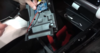
1. Grabbed a T20 driver, a 1/4” socket, and a 1/4” ratchet from my toolbox.
61214A55-B36B-4942-A751-9ABB6DD6775B.jpeg


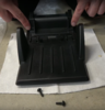
2. Looked down my center console with the flip door open to find the two screws from above.
E85B6A9D-939B-4B56-82A9-685CD2DE7DEA.jpeg


3. Closed the lid, and felt around blindly to place the T20 bit to the screw, then attached my ratchet to the socket. (I guess I should clean out my car. In my defense...how am I supposed to see the tissue?! That would’ve been there forever if not for this mod)

12EA5FA2-C603-4570-B98D-8253B3B69957.jpeg


4. Removed both screws. Had to remind myself this is facing me, so lefty loosey righty tighty wasnt right. Once the screws were out I stared at it as I wondered what I needed to pinch. Was it the sides? The bottom? Maybe I just pry the thing? Went back and watched or fast forwarded through Daerik’s video.

3CBB4FED-2A76-4B71-AEEC-F874390B506E.jpeg


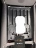
5. With the lid in an open position. I now knew it was hooks. I just pushed it from the bottom to slide the top part of the cover up towards the ceiling and it opened right up.

1880F6A9-8B6D-4C92-98FE-C963754C1593.jpeg


It becomes 2 pieces and I was able to get to work. Unfortunately there’s no way a 3 coil would fit. It’s just too thick.

77F50ABA-0BEF-435D-8DD9-5BBE728C811F.jpeg


D012FDC9-01F2-4490-8DC9-CE4936C43DA8.jpeg


So that’s it for me for now. Off to buy a single coil board.

PS: This post took more time than it did to get the lid apart
 

Attachments

  • 78D47122-F0F1-439C-A86B-E1AC60C90F05.jpeg
    78D47122-F0F1-439C-A86B-E1AC60C90F05.jpeg
    522.5 KB · Views: 157
It becomes 2 pieces and I was able to get to work. Unfortunately there’s no way a 3 coil would fit. It’s just too thick.

Thanks for sharing this, as I'd like to attempt this mod myself. Your picture of the 3 coil seems to show it on the wrong side of the lid. But then again, it looks like you have two different types of qi charger pcbs? One with the pcb mounted directly under the coils and the other off to the side?

I just bought a 3 coil and am going to give this a shot. I figured I can remove the coils from the plastic/metal backing to reduce the thickness, and will use one with the pcb off to the side to further improve that.
 
Thanks for sharing this, as I'd like to attempt this mod myself. Your picture of the 3 coil seems to show it on the wrong side of the lid. But then again, it looks like you have two different types of qi charger pcbs? One with the pcb mounted directly under the coils and the other off to the side?

The first picture with coil is against the top part of the lid (leathered part) so the coils should be pointing away from the leather, just as it's displayed. This would put the charging coils pointed towards the rear of the car when installed, against where your phone would go. I don't plan on mounting it here, just putting it here to show proportions of how wide a 3 coil would be. The 2nd picture is of the bottom part of the lid (plastic part) and where it would ultiamtely be mounted; also resulting in it pointing towards the rear of the car.

The PCB I have has enough room to be folded to be mounted under it as shown in the first picture with the board, or unfolded as shown in the 2nd picture with the board. It’s too thick when folded, and too long when it is unfolded.

I just bought a 3 coil and am going to give this a shot. I figured I can remove the coils from the plastic/metal backing to reduce the thickness, and will use one with the pcb off to the side to further improve that.

I actually just did that, With the backing removed, you can get it to squeeze in. Unfortunately, I'm not an EE; so I wasn't sure if this would cause issues since all the boards I saw have the backing. (ie, Does this reduce signal strength? Is it safe? Would it interfere with the board if I had it in a folded position?)
 
The first picture with coil is against the top part of the lid (leathered part) so the coils should be pointing away from the leather, just as it's displayed. This would put the charging coils pointed towards the rear of the car when installed, against where your phone would go. I don't plan on mounting it here, just putting it here to show proportions of how wide a 3 coil would be. The 2nd picture is of the bottom part of the lid (plastic part) and where it would ultiamtely be mounted; also resulting in it pointing towards the rear of the car.

Yeah, I figured you were just using that photo to show how it would fit width wise, even if you wouldn't mount it on that side of the lid.

The PCB I have has enough room to be folded to be mounted under it as shown in the first picture with the board, or unfolded as shown in the 2nd picture with the board. It’s too thick when folded, and too long when it is unfolded.

Ah, I see. I just bought a 3 coil qi charger on ebay that has the coils connected to the long side of the PCB, so you could potentially have the coils running horizontally with the PCB placed below it. This would alleviate your problem with it being too long, since you need to orient it vertically with the one you currently have.


I actually just did that, With the backing removed, you can get it to squeeze in. Unfortunately, I'm not an EE; so I wasn't sure if this would cause issues since all the boards I saw have the backing. (ie, Does this reduce signal strength? Is it safe? Would it interfere with the board if I had it in a folded position?)

Funny enough, I am an electrical engineer. There's certainly the possibility of EMI, but wouldn't be an issue with the configuration I found as I wouldn't be stacking them.
 
Last edited:
I just bought a 3 coil qi charger on ebay that has the coils connected to the long side of the PCB, so you could potentially have the coils running horizontally with the PCB placed below it. This would alleviate your problem with it being too long, since you need to orient it vertically with the one you currently have.

Do you have a link or picture if it? I was working with a Creazy 3 coil from Amazon

Funny enough, I am an electrical engineer. There's certainly the possibility of EMI, but wouldn't be an issue with the configuration I found as I wouldn't be stacking them.

That’s good to know. So is the board there mostly for structure and direct EMI protection?

I did some more tests, this time I cut some of the coils off to see if I could do some repositioning as well. I’ve concluded that the challenge isn’t necessarily the 3 coils - especially given your statement about the backing. It’s the length of wire to maneuver the board, ultimately leading to the USB power connector.

I’ll need to find a flat/thin connector because that alone is thicker than both the coils and the board combined.

Also, the minor thickness from 3 coils is only an issue if you have OCD. The extra curvature doesn’t prevent the lid from hooking and locking down. Once it’s closed, you can’t really tell the difference. The usb connector on the other hand prevents the lid from locking in place
 
Do you have a link or picture if it? I was working with a Creazy 3 coil from Amazon


That’s good to know. So is the board there mostly for structure and direct EMI protection?

I did some more tests, this time I cut some of the coils off to see if I could do some repositioning as well. I’ve concluded that the challenge isn’t necessarily the 3 coils - especially given your statement about the backing. It’s the length of wire to maneuver the board, ultimately leading to the USB power connector.

I’ll need to find a flat/thin connector because that alone is thicker than both the coils and the board combined.

Also, the minor thickness from 3 coils is only an issue if you have OCD. The extra curvature doesn’t prevent the lid from hooking and locking down. Once it’s closed, you can’t really tell the difference. The usb connector on the other hand prevents the lid from locking in place

This is the one I ordered.

Qi Wireless Charger PCBA Circuit Board With 3 Coil Wireless Charging Pad DIY 2A | eBay

Hopefully the PCB isn't too wide. Though this one may be better since the microUSB header is on its own tiny PCB that's wired to the main PCB. This would allow you to place that outside of the main lid sandwich.

2018 3 Coils Qi DIY Wireless Charger PCBA Circuit Board Coil Charger Micro USB | eBay

Are you saying that the microUSB header on the PCB is too thick? Or is it the microUSB cable connector that's too thick? Regardless, you could either order that second one, or likely even remove the header and solder the 5V and GND directly to the PCB (the data signals you can likely just ground since you'll be using it for power only and not data transfer)

The later. The cable - specifically the plastic around the connector is too thick. That second board looks like it would solve the issue, but may be too big. But for $8, worth a try.