


Welcome to Tesla Motors Club
Discuss Tesla's Model S, Model 3, Model X, Model Y, Cybertruck, Roadster and More.
Register
Install the app
How to install the app on iOS
You can install our site as a web app on your iOS device by utilizing the Add to Home Screen feature in Safari. Please see this thread for more details on this.
Note: This feature may not be available in some browsers.
-
Want to remove ads? Register an account and login to see fewer ads, and become a Supporting Member to remove almost all ads.
You are using an out of date browser. It may not display this or other websites correctly.
You should upgrade or use an alternative browser.
You should upgrade or use an alternative browser.
")
BTW, I am trying to find out any message on the canbus which the motor temperatures are included. Anyone has been able to get it? I have checked out some message IDs included in the Tesla Model S CAN Bus Deciphering document provided by wk057, but I have not found anything about that.
Any luck about that?
Many thanks!
Any luck about that?
Many thanks!
garygid
Member
There are 16 modules in the battery pack, and 32 temperatures are reported with the "cell" voltage data. So, we presume there are two temperatures for each module, probably a fluid in and fluid out temperature.
aguynamedsterl
New Member
Maybe I missed something (sorry if I did), but where did these scaling factors come from?For those that do not speak "code", the 8 data bytes (8 bits each) can be called D1, D2 ... D8.
The D1 value is an Index value, a counter for the 24 0x6F2 messages.
Each message has bytes D2 through D8 (7 bytes) used for 4 values, of 14 bits each.
So, string out the 8 bits of the 7 bytes as 8 x 7 = 56 bits, and use those bits, in groups
of 14 bits, as the 4 voltage (or temperature) values (14 x 4 = 56).
The 14 bits for the voltages are an unsigned integer. Multiply by 0.000305 to get cell voltage.
The 14 bits for the temperatures are a signed integer. Multiply by 0.0122 to get degrees C.
Thanks to wk057 for the exact scale factors.
I've actually got a few modules sitting in front of me and have interfaced with them over UART using an mbed microcontroller. I can read the cell voltage and temperature registers, but when I used the scaling specified above, my module voltages (sum of all 6 cell voltages) is too low by about 2V. Another resource (Model S BMS hacking) specifies a scaling for voltage of 0.000381493 if you dig through their Arduino code. This value gives me a module voltage that's too high.
What's odd is the discrepancy between each module's reported voltage and actual voltage measured with a DMM does not seem to be linear - applying a correction to make the scaling of the reported voltage match the actual voltage for any particular module will make the discrepancy greater for other modules.
I'm unsure if this is just a sensor issue or small inaccuracy in the voltage scaling.
DB 2
Member
Maybe I missed something (sorry if I did), but where did these scaling factors come from?
I've actually got a few modules sitting in front of me and have interfaced with them over UART using an mbed microcontroller. I can read the cell voltage and temperature registers, but when I used the scaling specified above, my module voltages (sum of all 6 cell voltages) is too low by about 2V. Another resource (Model S BMS hacking) specifies a scaling for voltage of 0.000381493 if you dig through their Arduino code. This value gives me a module voltage that's too high.
What's odd is the discrepancy between each module's reported voltage and actual voltage measured with a DMM does not seem to be linear - applying a correction to make the scaling of the reported voltage match the actual voltage for any particular module will make the discrepancy greater for other modules.
I'm unsure if this is just a sensor issue or small inaccuracy in the voltage scaling.
The scaling factors came from here.
You say you are interfaced over UART using an mbed microcontroller. I sure wish I knew what that meant, but I will suggest this possibility. You are reading the registers and applying the scaling factor. Perhaps the BMS reads the register and converts that output to a linear scale, and then broadcasts that converted value over the CANBus. The 0.000305 scaling applies to the CANBus reported value, not to the register value reported to the BMS. Just a thought, probably worth less than it costs.
Great! Thanks for the detailed information.
Hi mspohr,
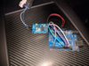
if you are still interested to make it work with arduino UNO and MCP2515.
I have just connected a CANbus MCP2515 chip (bought from ebay) to an Arduino UNO and could read loads of data from my tesla model S.
Paid around 1.5$ for the chip and used the following canbus arduino lib from fowler
https://github.com/coryjfowler/MCP_CAN_lib
You can easily use the examples already provided and filter by the message ID you like.
works like a charm. Don't forget to set the correct clock speed, on those cheap chips it's 8MHZ not 16MHZ.
So far I could read all battery information along with other stuff too, don't seem to miss any frames here.
Havent tried yet to capture data while driving, where most probably there will be more frames on the bus.
cheers
Attachments
mspohr
Well-Known Member
Thanks for this. I've ordered parts and will give it a try.Hi mspohr,
if you are still interested to make it work with arduino UNO and MCP2515.
I have just connected a CANbus MCP2515 chip (bought from ebay) to an Arduino UNO and could read loads of data from my tesla model S.
Paid around 1.5$ for the chip and used the following canbus arduino lib from fowler
https://github.com/coryjfowler/MCP_CAN_lib
You can easily use the examples already provided and filter by the message ID you like.
works like a charm. Don't forget to set the correct clock speed, on those cheap chips it's 8MHZ not 16MHZ.
So far I could read all battery information along with other stuff too, don't seem to miss any frames here.
Havent tried yet to capture data while driving, where most probably there will be more frames on the bus.
cheers
Thanks for this. I've ordered parts and will give it a try.
I got this one, from that supplier.
MCP2515 TJA1050 EF02037 CAN Bus Shield Receiver SPI Controller IC for Arduino | eBay
Oh yes and you cant reuse collin s code as is.
I can share the code for arduino uno which works with the library posted above.
The code just displays the battery cells voltages and temperatures in a similar way as collins one.
Basically it reads the 14 bits values from the 56bits number contained in a canbus frame and converts them into voltages values.
A big thanks to collin for deciphering id 6F2 and jason for the conversion factor :14bit to real voltage.
Cheers
mspohr
Well-Known Member
Would like to get your Arduino code. ThanksI got this one, from that supplier.
MCP2515 TJA1050 EF02037 CAN Bus Shield Receiver SPI Controller IC for Arduino | eBay
Oh yes and you cant reuse collin s code as is.
I can share the code for arduino uno which works with the library posted above.
The code just displays the battery cells voltages and temperatures in a similar way as collins one.
Basically it reads the 14 bits values from the 56bits number contained in a canbus frame and converts them into voltages values.
A big thanks to collin for deciphering id 6F2 and jason for the conversion factor :14bit to real voltage.
Cheers
Jack, do you happen to know at what "Tesla SoC" your screenshot was taken? I see a cell voltage between 3.89 and 3.91 with 3.899V as the average.
What I have been trying to find out is at what "Tesla SoC" the cells are at 3.92V. I would like to set this SoC as my daily charge level when I don't need the range.
According to this article on the Battery University website: "In terms of longevity, the optimal charge voltage is 3.92V/cell. Battery experts believe that this threshold eliminates all voltage-related stresses; going lower may not gain further benefits but induce other symptoms."
Hi Jpet,
i get a SoC of 67% for voltages around 3.925 V. It was 62% around 3.90V, measured shortly after charging.
basically the range seems to be between 60%-70% for those voltages.
cheers
Would like to get your Arduino code. Thanks
considering that an arduino uno costs around 10$ and the CAN bus chip 1.5$, it does what's supposed to do.
it processes all battery frames, always and will display all voltages cells and temperatures, without issues.
if you want to do more processing in the code and output to serial monitor more info, then the arduino uno (atmega) isn't fast enough.
For example, I noticed that if I print too many variables to serial monitor then the arduino will slow down too much and can't catch up with frames.
But as I said, for the purpose of displaying BMS info, it works.
enjoy
Attachments
mspohr
Well-Known Member
Thanks very much. Looks good.considering that an arduino uno costs around 10$ and the CAN bus chip 1.5$, it does what's supposed to do.
it processes all battery frames, always and will display all voltages cells and temperatures, without issues.
if you want to do more processing in the code and output to serial monitor more info, then the arduino uno (atmega) isn't fast enough.
For example, I noticed that if I print too many variables to serial monitor then the arduino will slow down too much and can't catch up with frames.
But as I said, for the purpose of displaying BMS info, it works.
enjoy
I'll see what I can get out of it as far as throughput and not try to do too much on the Arduino.
CAN RECEIVED like this 6F2 00F2717C0C1FC7C7
CAN RECEIVED like this 6F2 00F2717C0C1FC7C7
Reverse order: C7 C7 1F 0C 7C 71 F2 00
(8) (7) (6) (5)(4) (3) (2) (valuebb1(i))
In binary: 11000111110001 11000111110000 11000111110001 11000111110010 00000000
14bits this And &H3FFF) * 0.000305 this 'And &H3FFF) .................. ....................... (not needed)
Explained in plain visualisation
Code:
    For i As Integer = 1 To 8
                            value0bb1(i) = Convert.ToByte(newCommand.Substring(((i * 2) + 1), 2), 16)
                        Next

                        Dim value0bbit As Integer = (value0bb1(8) << 8) + value0bb1(7)              'joining  C700 (shifted left) + C7 to get C7C7, shift this right 2 times
                        Dim value1bbit As Integer = (value0bb1(7) << 16) + (value0bb1(6) << 8) + value0bb1(5)
                        Dim value2bbit As Integer = (value0bb1(5) << 16) + (value0bb1(4) << 8) + value0bb1(3)
                        Dim value3bbit As Integer = (value0bb1(3) << 8) + value0bb1(2)

                        Dim izracunaj0bb1 As Double = ((value0bbit >> 2) And &H3FFF) * 0.000305         ..naj0bb1 (bat 1)
                        Dim izracunaj1bb1 As Double = ((value1bbit >> 4) And &H3FFF) * 0.000305     ..naj2bb1 (bat 2)
                        Dim izracunaj2bb1 As Double = ((value2bbit >> 6) And &H3FFF) * 0.000305       ..naj2bb1 (bat 3)
Dim izracunaj3bb1 As Double = (value3bbit And &H3FFF) * 0.000305 ..naj3bb1 (bat 4)Reverse order: C7 C7 1F 0C 7C 71 F2 00
(8) (7) (6) (5)(4) (3) (2) (valuebb1(i))
In binary: 11000111110001 11000111110000 11000111110001 11000111110010 00000000
14bits this And &H3FFF) * 0.000305 this 'And &H3FFF) .................. ....................... (not needed)
Explained in plain visualisation
Similar threads
- Replies
- 10
- Views
- 1K
- Replies
- 4
- Views
- 239
- Replies
- 3
- Views
- 1K
- Replies
- 13
- Views
- 1K