Part 2
Be careful with the plastic screws - mine were ok but I can imagine if they have suffered a lot of heat cycles they could become brittle....


Disconnect this small wire that disappears down into lower board. Mine had some sticky tape attaching it to 1 of the capacitors.

Lift the board free...

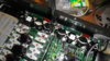
This is how it looks now... The left side of the black choke (I think that is what it is called on the left side of this picture) you should remove the nyloc nut holding the left side - the bolt for this nut is actually threaded into the fitting.

You should unscrew this bolt until it is flush with the threaded fitting. This will allow the board to be lifted clear.
In the photo below remove the megapole board with the removable fuse on it by removing the 2 crimp connectors screwed onto the frame and right front clamp. (2 white cables with red crimps)

Now start to undo the nuts on the clamps - I think they are 6mm. In my case all the nuts were loctited onto the studs and it was the studs underneath that started to come out. Thats ok but only do a turn or 2 on each nut before proceeding to the next 1. If you go too much on 1 nut the nut underneath will start to push up on the circuit board from underneath and may damage things...go slowly and work your way around until they are all loose. If one stud gets tight then move onto its neighbour...You can check the board to see if it is loose or not.

The board is now loose and can be lifted up. Be careful there is a cable going down to the heat sink - be careful with this. The terminal clip would not fit through the hole in the board to be able to lift it clear.

Without touching the wire take a small square sectioned file and gently file the hole slightly larger so you can get the terminal through the hole which will allow you to get the board fully clear of the PEM.

OK that's the 1st board removed!!!
Now you can look at the state of your insulation...

Now remove the smaller upper circuit board on the centre main board - same as the 1st one. Notice there are no long plastic screws on this one. Remove the small terminal connector that goes to the "choke" board. You have to remove this board as it is covering some of the IGBD's on the centre board. See the following photos...
Oops - next thread...
Be careful with the plastic screws - mine were ok but I can imagine if they have suffered a lot of heat cycles they could become brittle....
Disconnect this small wire that disappears down into lower board. Mine had some sticky tape attaching it to 1 of the capacitors.
Lift the board free...
This is how it looks now... The left side of the black choke (I think that is what it is called on the left side of this picture) you should remove the nyloc nut holding the left side - the bolt for this nut is actually threaded into the fitting.
You should unscrew this bolt until it is flush with the threaded fitting. This will allow the board to be lifted clear.
In the photo below remove the megapole board with the removable fuse on it by removing the 2 crimp connectors screwed onto the frame and right front clamp. (2 white cables with red crimps)
Now start to undo the nuts on the clamps - I think they are 6mm. In my case all the nuts were loctited onto the studs and it was the studs underneath that started to come out. Thats ok but only do a turn or 2 on each nut before proceeding to the next 1. If you go too much on 1 nut the nut underneath will start to push up on the circuit board from underneath and may damage things...go slowly and work your way around until they are all loose. If one stud gets tight then move onto its neighbour...You can check the board to see if it is loose or not.
The board is now loose and can be lifted up. Be careful there is a cable going down to the heat sink - be careful with this. The terminal clip would not fit through the hole in the board to be able to lift it clear.
Without touching the wire take a small square sectioned file and gently file the hole slightly larger so you can get the terminal through the hole which will allow you to get the board fully clear of the PEM.
OK that's the 1st board removed!!!
Now you can look at the state of your insulation...
Now remove the smaller upper circuit board on the centre main board - same as the 1st one. Notice there are no long plastic screws on this one. Remove the small terminal connector that goes to the "choke" board. You have to remove this board as it is covering some of the IGBD's on the centre board. See the following photos...
Oops - next thread...