


Welcome to Tesla Motors Club
Discuss Tesla's Model S, Model 3, Model X, Model Y, Cybertruck, Roadster and More.
Register
Install the app
How to install the app on iOS
You can install our site as a web app on your iOS device by utilizing the Add to Home Screen feature in Safari. Please see this thread for more details on this.
Note: This feature may not be available in some browsers.
-
Want to remove ads? Register an account and login to see fewer ads, and become a Supporting Member to remove almost all ads.
You are using an out of date browser. It may not display this or other websites correctly.
You should upgrade or use an alternative browser.
You should upgrade or use an alternative browser.
Another product I ordered in the meantime is this one:
Gap Pad 5000S35 Features ~ Thermal Materials, Thermal Solutions ~ Henkel
That has excellent property in the range, but only 5 W/mK on the other hand it is electrically insulating.
This is interesting. Thermal conductivity is similar to the original insulation as Daniel mentioned. Any worry about the polymer creeping and eventually deforming under pressure/temperature as it seems quite soft? It is fiberglass reinforced, so this may help. However, this may be interesting in a thin form ( 20-50 microns thick to eliminate thermal penalty) as a gap filler and very nice mechanical buffer between a ceramic sink and the metal cooling plate to absorb thermal expansion mismatch. This may also be interesting on the top of the ceramic between the IGBT. Also like the continuous use temp of 392C..
DanielFriederich
Member
Maximum operation heat for the igbts is 150 - 175 deg. C. depending on manufacturer.
Since I haven't been able until now to determine the exact electroncs part Tesla used as igbt I am not sure about the changes of the replacement parts. In the German Forum the Infineon IKW75N60T was mentioned as an replacement. There are other manufacturers with the same replament values like Fairchild and IXYS. Those parts a slightly different in max. operation temp, saturation voltage and max. output...
As far as I can judge the original used insulation has been between 0,25 - 0,5 mm in thickness.
The ceramic isolation combined with some ceramic grease (as done on processors) is the way my technician wants to do it....
We'll see...
Water cooling has already been discussed and would require big changes in design and also controlling; maybe even of the software to which we dont have access to.
3 Phases
I posted a thread here in the forum about a austrian guy who had developed a 3 phase to 1 phase converter suitable to be stored in the trunk of the Roadster")
Since I haven't been able until now to determine the exact electroncs part Tesla used as igbt I am not sure about the changes of the replacement parts. In the German Forum the Infineon IKW75N60T was mentioned as an replacement. There are other manufacturers with the same replament values like Fairchild and IXYS. Those parts a slightly different in max. operation temp, saturation voltage and max. output...
As far as I can judge the original used insulation has been between 0,25 - 0,5 mm in thickness.
The ceramic isolation combined with some ceramic grease (as done on processors) is the way my technician wants to do it....
We'll see...
Water cooling has already been discussed and would require big changes in design and also controlling; maybe even of the software to which we dont have access to.
3 Phases
I posted a thread here in the forum about a austrian guy who had developed a 3 phase to 1 phase converter suitable to be stored in the trunk of the Roadster
Kerios
Member
This has been a really good thread so far, and the discussion about a replacement PEM / redesign has come up before. I believe some guys in Latvia who have a Roadster for hill climbs have designed smaller replacement PEM with improved performance, whilst we know the Model S has both supercharge capability and water cooling for the power electronics.
There is also the QCP JdeMo modification currently being shipped and installed I think, which dupes the car into thinking it is in regen mode thus to use DC rather than AC and so fast charge.
I wonder however, based on the high level of knowledge demonstrated in this thread (electronics, material science, power distribution etc), whether it would be possible for us to design a replacement PEM with the features we desire, and the resilience needed to ensure the car remains viable for the next decade plus.
Without doubt I think, we are seeing that the PEM (more so for the later cars), is the Achilles heel - the motor, battery and other vehicle subsystems seem pretty solid. My roadster has gone through four PEMs in 15 months - and whilst the current re-manufactured one is under warranty for the next 12 months, I worry about what happens after that.
Features I think which are desirable (and could be incorporated easily), would be the following, in no particular order:
1. Water cooled electronics, replacing the need for the blower fan
2. Fast DC charging - opportunity to switch out the charging port for a Type 2 perhaps?
3. Easily removable / demount-able connections for PEM removal - but removal of air cooling would perhaps remove
the need for the annual PEM removal etc.
4. Replaceable IGBT boards as modules with appropriately rated connectors and good thermal materials
5. Uprated connectors for the PEM cooling fan / motor fan if appropriate
6. WiFi or Bluetooth etc link for monitoring of PEM to supplement or replace OVMS
7. Higher power rating for IGBTs etc
8. At least two suppliers for all key components for legacy purposes
9. Plug and play with existing PEM connectors.
Not a trivial task, but one which would see the life potential of the car protected, whilst reducing the wait times we see with the SC's due to PEM shortages etc.
Thoughts?
Although the average of the 3 are shown,I wonder if each is monitored separately for a temperature fault. Would be nice to see if one plate is running significantly hotter than the others
Pretty sure that they are, as I have seen a megapole temp mismatch error on the VDS before.
Michael1227
Member
The three modules with each 28 IGBT IKW75N60T (Infineon) original parts in my PEM (Tesla roadster 2.5!) Are monitored by each a temperature sensor located almost in the middle of the cooling plate, but one of them Did not detect the overheating and bursting of one of the IGBTs.
As regards the original thermal paste, it is electrically insulating, contains no fiberglass cloth, and must be 0.5 mm thick at the origin.
The Gap Pad 5000S35 to a fiber with not very tight mesh (0.5x2mm), but on the surface if the IGBT elements are well welded flat, the pressure applied directly on their backs through the circuit (aluminum parts) ) Is not excessive. The effective thermal property and the high performance dielectric should do the trick.
CHECK THE AIR COOLING CIRCUIT AND THE WINDS OF YOUR RADIATORS ESPECIALLY ON THE RIGHT OF THE PEM SEEN FROM THE REAR (I do not think we can clean the PEM well in a TESLA service! And opening the PEM is not sufficient, it is necessary to disassemble all the connections to remove the support of plate IGBT doing sheath of ventilation)
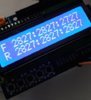
I just finished a small editing with an Arduino circuit and 12 sensors to closely monitor my IGBT circuits. Two front and two back aligned between the 6 columns of IGBT, the temperature is displayed on a small LCD screen of two lines. I go up my PEM next week and keep you up to date.
As regards the original thermal paste, it is electrically insulating, contains no fiberglass cloth, and must be 0.5 mm thick at the origin.
The Gap Pad 5000S35 to a fiber with not very tight mesh (0.5x2mm), but on the surface if the IGBT elements are well welded flat, the pressure applied directly on their backs through the circuit (aluminum parts) ) Is not excessive. The effective thermal property and the high performance dielectric should do the trick.
CHECK THE AIR COOLING CIRCUIT AND THE WINDS OF YOUR RADIATORS ESPECIALLY ON THE RIGHT OF THE PEM SEEN FROM THE REAR (I do not think we can clean the PEM well in a TESLA service! And opening the PEM is not sufficient, it is necessary to disassemble all the connections to remove the support of plate IGBT doing sheath of ventilation)
I just finished a small editing with an Arduino circuit and 12 sensors to closely monitor my IGBT circuits. Two front and two back aligned between the 6 columns of IGBT, the temperature is displayed on a small LCD screen of two lines. I go up my PEM next week and keep you up to date.
Attachments
Michael1227
Member
This has been a really good thread so far, and the discussion about a replacement PEM / redesign has come up before. I believe some guys in Latvia who have a Roadster for hill climbs have designed smaller replacement PEM with improved performance, whilst we know the Model S has both supercharge capability and water cooling for the power electronics.
There is also the QCP JdeMo modification currently being shipped and installed I think, which dupes the car into thinking it is in regen mode thus to use DC rather than AC and so fast charge.
I wonder however, based on the high level of knowledge demonstrated in this thread (electronics, material science, power distribution etc), whether it would be possible for us to design a replacement PEM with the features we desire, and the resilience needed to ensure the car remains viable for the next decade plus.
Without doubt I think, we are seeing that the PEM (more so for the later cars), is the Achilles heel - the motor, battery and other vehicle subsystems seem pretty solid. My roadster has gone through four PEMs in 15 months - and whilst the current re-manufactured one is under warranty for the next 12 months, I worry about what happens after that.
Features I think which are desirable (and could be incorporated easily), would be the following, in no particular order:
1. Water cooled electronics, replacing the need for the blower fan
2. Fast DC charging - opportunity to switch out the charging port for a Type 2 perhaps?
3. Easily removable / demount-able connections for PEM removal - but removal of air cooling would perhaps remove
the need for the annual PEM removal etc.
4. Replaceable IGBT boards as modules with appropriately rated connectors and good thermal materials
5. Uprated connectors for the PEM cooling fan / motor fan if appropriate
6. WiFi or Bluetooth etc link for monitoring of PEM to supplement or replace OVMS
7. Higher power rating for IGBTs etc
8. At least two suppliers for all key components for legacy purposes
9. Plug and play with existing PEM connectors.
Not a trivial task, but one which would see the life potential of the car protected, whilst reducing the wait times we see with the SC's due to PEM shortages etc.
Thoughts?
1. Quite imaginable, but unless you connect to the battery cooling system if the temperatures are compatible, it will require a fan and a radiator ..!)
2. Tony did it, (CHADEMO) but you have to stay in the car during the load.
3. Screw terminals cheaper than sockets..and safer ..
4. It works, the circuit is not very complex and the parts not very expensive.
5. Above all, ask DYSON how to make a bagless vacuum cleaner!
6. WiFi or Bluetooth etc. link for monitoring of PEM to supplement or replace OVMS .. arduino with wires in the meantime ..
7. As we have the data sheet of the current IGBT, it is enough to find an engineer in IGBT to find us the replacement.
8. I would say .. the PEM schemas from TESLA
9. Plug and play with existing PEM connectors.
10. It is necessary to share the information to advance on the subject!
Have a nice day !
Michael
Michael1227
Member
Maximum operation heat for the igbts is 150 - 175 deg. C. depending on manufacturer.
Since I haven't been able until now to determine the exact electroncs part Tesla used as igbt I am not sure about the changes of the replacement parts. In the German Forum the Infineon IKW75N60T was mentioned as an replacement. There are other manufacturers with the same replament values like Fairchild and IXYS. Those parts a slightly different in max. operation temp, saturation voltage and max. output...
As far as I can judge the original used insulation has been between 0,25 - 0,5 mm in thickness.
The ceramic isolation combined with some ceramic grease (as done on processors) is the way my technician wants to do it....
We'll see...
Water cooling has already been discussed and would require big changes in design and also controlling; maybe even of the software to which we dont have access to.
3 Phases
I posted a thread here in the forum about a austrian guy who had developed a 3 phase to 1 phase converter suitable to be stored in the trunk of the Roadster
With an autotransformer it is necessary to count 70 Kg! With power electronics? How much power is it able to transform?
I explored this track, but the battery pack of the roadster is very powerful, it would be necessary to ensure maximum load values in DC, soon there will be terminals everywhere .. up to 150 KW/h which is too much for us !!
Not a trivial task, but one which would see the life potential of the car protected, whilst reducing the wait times we see with the SC's due to PEM shortages etc.
Thoughts?[/QUOTE]
What you list would be great. Liquid cooling is the long ball, I would be fantastically happy just to have the chronic failure points not replaced, but improved. As you note:
1. IGBT thermal conductor/electronic insulator
2. The Fan motor connectors
3. Improved thermal monitoring (as per Michael)
Second level would be keep the air cooling, but possibly redesign airflow and sinks for better cooling efficiency.
Enjoyable link on the power electronics and choice of legacy IGBTs (similar to roadster) related to the S (apologies if this was posted before):
In a Tesla model S, there is no IGBT packaging trick.
Thoughts?[/QUOTE]
This has been a really good thread so far, and the discussion about a replacement PEM / redesign has come up before. I believe some guys in Latvia who have a Roadster for hill climbs have designed smaller replacement PEM with improved performance, whilst we know the Model S has both supercharge capability and water cooling for the power electronics.
There is also the QCP JdeMo modification currently being shipped and installed I think, which dupes the car into thinking it is in regen mode thus to use DC rather than AC and so fast charge.
I wonder however, based on the high level of knowledge demonstrated in this thread (electronics, material science, power distribution etc), whether it would be possible for us to design a replacement PEM with the features we desire, and the resilience needed to ensure the car remains viable for the next decade plus.
Without doubt I think, we are seeing that the PEM (more so for the later cars), is the Achilles heel - the motor, battery and other vehicle subsystems seem pretty solid. My roadster has gone through four PEMs in 15 months - and whilst the current re-manufactured one is under warranty for the next 12 months, I worry about what happens after that.
Features I think which are desirable (and could be incorporated easily), would be the following, in no particular order:
1. Water cooled electronics, replacing the need for the blower fan
2. Fast DC charging - opportunity to switch out the charging port for a Type 2 perhaps?
3. Easily removable / demount-able connections for PEM removal - but removal of air cooling would perhaps remove
the need for the annual PEM removal etc.
4. Replaceable IGBT boards as modules with appropriately rated connectors and good thermal materials
5. Uprated connectors for the PEM cooling fan / motor fan if appropriate
6. WiFi or Bluetooth etc link for monitoring of PEM to supplement or replace OVMS
7. Higher power rating for IGBTs etc
8. At least two suppliers for all key components for legacy purposes
9. Plug and play with existing PEM connectors.
Not a trivial task, but one which would see the life potential of the car protected, whilst reducing the wait times we see with the SC's due to PEM shortages etc.
Thoughts?
What you list would be great. Liquid cooling is the long ball, I would be fantastically happy just to have the chronic failure points not replaced, but improved. As you note:
1. IGBT thermal conductor/electronic insulator
2. The Fan motor connectors
3. Improved thermal monitoring (as per Michael)
Second level would be keep the air cooling, but possibly redesign airflow and sinks for better cooling efficiency.
Enjoyable link on the power electronics and choice of legacy IGBTs (similar to roadster) related to the S (apologies if this was posted before):
In a Tesla model S, there is no IGBT packaging trick.
DanielFriederich
Member
Update:
Been at the guy taking a look on the dissaseblemd PEM...
as promised here some pictures of the megapoles and driver boards as well as the "additional" parts


Been at the guy taking a look on the dissaseblemd PEM...
as promised here some pictures of the megapoles and driver boards as well as the "additional" parts
DanielFriederich
Member


Hello,
Thanks for the picutres. What will you do then, repair the PEM yourself?
DanielFriederich
Member
The idea is to replace the worn out insulation and to replace all transistors (done by a certified electronic technician) for a friction of the costs when done by Tesla or other 3rd party
DanielFriederich
Member
Just a little update - I have removed my PEM and opened it up to have a little look. No obvious sign of damage, no burnt smell BUT I have noticed that the fuse on Megapole circuit board is blown.
Does anyone know what or if anything can be drawn from this?View attachment 231264
600 Volt, 50 kA
just looked it up this morning
600 Volt, 50 kA
just looked it up this morning
Is it really 50,000 amps? Sounds big enough for a power station...but what do I know...
DanielFriederich
Member
V * A = WIs it really 50,000 amps? Sounds big enough for a power station...but what do I know...
Roadster produces 215 kW = 215.000 W
215.000 W / 400 V (average Voltage) = 537,5 A
(when I remember right the max amp drawn in the Roadster is 750 A)
I looked up the photo of the fuse closely and it really states:
U11
600V DC IR 50kA
www.bussmann.com
DanielFriederich
Member
and another update:
Technician called:
- originally used IGBTs are Infinieon IKT75N60T
- insulation at some parts completely gone due to aging and overheating
for my car especially:
- first megapol circuit board all transistor ok (measured)
- no visible damage on cooling plate
- guy will solder the parts again and try to use the alloy oxide ceramic insulation plates
conclusions:
-in the 1.5 PEM a higher level Infineon is used compared to the 2.0 and 2.5
despite the fact that the driver ICs are capable of running a pulse width modulation of 32 kHz it should be lower since the Infineon goes up to 20 kHz only
- I had Phase A and B error... the first board was completely ok... so if on the second board there's no blown transistor I'm screwed
keep the fingers crossed guys!
DaveD
EVs Kick Gas!
Are you going to replace the electrolytic caps in the PEM, particularly the megapole ones? It's my understanding that they have a finite lifetime.
dhrivnak
Active Member
I have read that the fuses can sometime blow. Poor tolerances, a bad fuse or a lot of high usage. So buy two fuses and if it blows again then you do have a problem. But I have not read about repeated fuse problems.Just a little update - I have removed my PEM and opened it up to have a little look. No obvious sign of damage, no burnt smell BUT I have noticed that the fuse on Megapole circuit board is blown.
Does anyone know what or if anything can be drawn from this?View attachment 231264
Similar threads
- Replies
- 5
- Views
- 360
- Replies
- 23
- Views
- 3K
- Replies
- 2
- Views
- 1K