Welcome to Tesla Motors Club
Discuss Tesla's Model S, Model 3, Model X, Model Y, Cybertruck, Roadster and More.
Register

Some questions about 14-50 receptacles

This site may earn commission on affiliate links.
I've just pulled out my installation manual for my HPWC.
It seems to say that you should set the DIP switches to the maximum current supplied to the vehicle, not the circuit breaker rating.
Pretty sure the OP is talking about a Gen 3 unit and not a Gen 2. Unfortunately, people continue use the term HPWC when referring to the Gen 3 Wall Connector. In the case of a Gen 3 you set it to the circuit, in the case of a Gen 2, you are correct.
 
  • Like
Reactions: MacO512
Yes, but that is not normal for a 240 volt circuit. You are listing the exception.

Having trouble following you. What is a “normal” 240 volt circuit? There are circuits wired as 120/240 such as a 14-50 or 14-30, and 240 volt only circuits such as 6-20, 6-50, and of course hardwired which are almost always 240 only.
 
Yes, but that is not normal for a 240 volt circuit. You are listing the exception.
Many people purposefully use or build these "exceptions" for EV charging, as was discussed in this thread.

Perhaps 14-50's are more common, but that is not the only recepticle used or available. The fact that Tesla itself sells official adapters for 6-15, 6-20, and 6-50 shows that these are very normal commonly used receptacles.
 
  • Like
Reactions: GSP and mspohr
From the Wall connector manual:

Wall Connector includes integrated GFCI protection - do not install a GFCI circuit breaker.

NEC: https://www.dli.mn.gov/sites/default/files/pdf/NECFAQ20.pdf

However changes in 2020 Mandated GFCI for a plug on NEW INSTALLATIONS, but not the appliance. Hard wired EVSE equipment is exempted from this requirement.
If you read post 37, the paragraph where GFCI was being priced was if there was a 14-50 outlet going in.
 
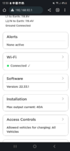
OP: I'm sure this has been covered but here is the UI for the Gen 3 wall connector. When you first power the unit up, you'll need to login to the unit via wifi and set the current. Since I'm running 40A continuous thru 50A breaker, my setting is 50A. If your breaker is 20A, you'd set 16A.

Feel free to post some photos of your current setup (before pulling the water heater) and im sure you can get some ideas. Most of the time, the breaker boxes are inside the garage so it'd actually be same price or cheaper to run a dedicated new circuit off a 50A breaker. I installed two wall connectors recently though im not an electrician.

1670203246234.png
 

Attachments

  • 1670203180250.png
    1670203180250.png
    305.9 KB · Views: 74
To clarify that... there should be only one cable coming into the box, with three conductors(white/black/ground). Note that its not foolproof, an outlet at the end of a chain of outlets will pass this test even though there are other things in the chain. This means its only an easy way to determine that an outlet is NOT dedicated.

Yes indeed.

Space heaters do not HAVE to be on a dedicated circuit, but I think doing so would be typical. Moreover, this is a 240V circuit so any receptacle would stand out as being different from the garden variety ones in the house. The only remaining possibility would be another hard wired device on the same circuit.
 
OP: I'm sure this has been covered but here is the UI for the Gen 3 wall connector. When you first power the unit up, you'll need to login to the unit via wifi and set the current. Since I'm running 40A continuous thru 50A breaker, my setting is 50A. If your breaker is 20A, you'd set 16A.

Feel free to post some photos of your current setup (before pulling the water heater) and im sure you can get some ideas. Most of the time, the breaker boxes are inside the garage so it'd actually be same price or cheaper to run a dedicated new circuit off a 50A breaker. I installed two wall connectors recently though im not an electrician.
Slight correction; if your breaker is 20A, you'd set 20A in the WC setup; but output would be limited by the WC at 16A.
 
  • Like
Reactions: SageBrush
Wall Connector has been installed and no issues other than connecting to the wifi with my phone. Needed to disable private relay on my phone to get it to connect. Thanks again to everyone for the helpful feedback.

Since the original wire was already routed to the wall heater, they just spliced it with some extra Romex 12-2 and punched a tiny hole to feed it into the wire box. Pretty straight forward. Set the Wall Connector to 20A (16A) and it's performing more than twice as fast as a 5-15.

IMG_8300.JPG
 
Last edited:
I may be interpreting your photo wrong, but it looks to me like you have mounted the wall connector inside the living space and are running the cord through the door into the garage when charging. The door into the garage is required to be fire rated and gasketed to prevent gasoline fumes and fire from entering your house so quickly. I'm confident that such an install would not pass inspection, and encourage you to spend the time and effort to properly mount the wall connector in the garage.
 
I may be interpreting your photo wrong, but it looks to me like you have mounted the wall connector inside the living space and are running the cord through the door into the garage when charging. The door into the garage is required to be fire rated and gasketed to prevent gasoline fumes and fire from entering your house so quickly. I'm confident that such an install would not pass inspection, and encourage you to spend the time and effort to properly mount the wall connector in the garage.
Well that's disconcerting. Your interpretation is correct. The picture is from a foyer/stairwell (1 flight) that leads to another door upstairs to the apartment. The cable runs through the doorway leaving it slightly ajar.

The garage is small and we have parked gas vehicles in there in the past but now it's just the MY. We don't store anything else in there other than a spare table and some tools. AFAIK there haven't been any gas leaks etc however I do understand the risks and now I'm worried. Sigh. Will look into this some more.
 
  • Like
Reactions: Pianewman
Well that's disconcerting. Your interpretation is correct. The picture is from a foyer/stairwell (1 flight) that leads to another door upstairs to the apartment. The cable runs through the doorway leaving it slightly ajar.

The garage is small and we have parked gas vehicles in there in the past but now it's just the MY. We don't store anything else in there other than a spare table and some tools. AFAIK there haven't been any gas leaks etc however I do understand the risks and now I'm worried. Sigh. Will look into this some more.
I would have said something sooner, but did not pick up on this aspect of the install earlier in the thread. A Tesla is not a huge fire risk, no more so than a gasoline car, but that's not a zero risk. You don't have a long ways to run that wire to get to the garage wall, but it will require opening more drywall.

Also remember that if you have to create a junction (splice wire), in order to reach the garage, you will need an accessible junction box to hold it. You can't just bury the junction inside the wall.
 
  • Like
Reactions: Eric33432
I would have said something sooner, but did not pick up on this aspect of the install earlier in the thread. A Tesla is not a huge fire risk, no more so than a gasoline car, but that's not a zero risk. You don't have a long ways to run that wire to get to the garage wall, but it will require opening more drywall.

Also remember that if you have to create a junction (splice wire), in order to reach the garage, you will need an accessible junction box to hold it. You can't just bury the junction inside the wall.
Right...Currently, the splice resides in the housing behind the wall heater. The electrician didn't mention anything about addressing the splice. I know you're talking about a run to the garage, not the current set up, but I figured it was worth mentioning.

Ugh, well crap. I might have to make some phone calls and see if I can find a good price to run it into the garage.

Thanks again for the feedback.