Has anyone mentioned that Tesla will likely ask folk to wear a hat with 8 cameras whilst doing tasks to record their work? - creates video clips and allows the Bot to practice shadow mode.


Welcome to Tesla Motors Club
Discuss Tesla's Model S, Model 3, Model X, Model Y, Cybertruck, Roadster and More.
Register
Install the app
How to install the app on iOS
You can install our site as a web app on your iOS device by utilizing the Add to Home Screen feature in Safari. Please see this thread for more details on this.
Note: This feature may not be available in some browsers.
-
Want to remove ads? Register an account and login to see fewer ads, and become a Supporting Member to remove almost all ads.
You are using an out of date browser. It may not display this or other websites correctly.
You should upgrade or use an alternative browser.
You should upgrade or use an alternative browser.
Tesla humanoid robot
- Thread starter Buckminster
- Start date
ucmndd
Well-Known Member
Yeah that’s what we need, a Tesla robot phantom braking in the hallway because there’s a cobweb overhead.

Sorry all I could see when he announced that is $$$ in future Tesla stock. God, I am sure glad to be a shareholder.
Tell me about it. I am so damn proud to own shares in Tesla, makes me smile with pride.
Oh and the wealth isn't too bad either.

UkNorthampton
TSLA - 12+ startups in 1
Might be wrong video, he did 2 due to tech issues - click on link & check out other videos by Warren to see 2nd James Douma videoWarren is talking a lot about the bot in the first hour:
2
22522
Guest
All,
I am no robot expert. But a straw-man vetting model to see how fast Tesla could make a humanoid robot if they wanted to leverage their optically coupled AI engine to control hand motions made sense for an investor forum. When I have significant financial investments, I need to do a plausibility test on claims out of due diligence.
Comments about robots do not belong in the investment forum, so this post is a comment anchor for the investing forum vetting post.
There are links to background posts when trying to sort out the motors and the humanoid part - they are ponderings. Then the images from the last post will be in this post to mover further conversation here.
This is the most important one as it defines humanoid: your post
This one takes the humanoid definition of a forearm, makes a surface model the arm and locates disc motors that look like pulley wheels on 2 stator (stationary) shafts. The larger diameter motors rotate to pull tendons that run up the inside of the wrist. The shaft with only small diameter motors is for pulleys that pass into the back of the hand. The shafts are displaced to match the muscle bulk distribution in an human forearm: your post
This one shows how to aggregate all hand, finger and lateral wrist information into a single camera image for the AI engine process. Really the important one for time to market. IFF they can't do it all with feedback from the motors: your post
Here is the anchoring text:
Here is my guess on the fast way to catch the rocket to Mars:
1) Internal illumination is needed inside the hermetically sealed optical cavity. The outside of the glass is painted, except for the bottoms of the grooves that the Dynema tendons run in that are ground smooth.
2) The camera folks have to have a chance to be successful. The optical path goes from the marker on the tendon off a mirrored surface on the wide end of the optical cavity toward the elbow, and then back to the cameras on the wrist end of the optical cavity. All the visual information for the entire hand is presented off that back face for both the redundant cameras to collect and send on to the AI processor. There are 3 chances for lens actions to help: the glass wall immediately under the the tendon, the mirrored back wall of the cavity, and the camera lens itself. The long path should help make the camera lens design a center of the process window activity.
3) It is a clamshell design with two mirrored parts that fit perfectly into the surface modeled forearm from the previous post, but since I don't know how to do internal illumination, most of these pictures are with one half removed to use ambient illumination.


And though the camera's eye. The back plate angle may need some adjustment, if not curvature. Could probably dolly the rendering camera all the way into the glass, but it would make even less sense than this one.

I don't know if they even need this. A hand full of hypodermic needle shaped motors with accordion dust seals on the tendons to keep dust away from the encoders (or whatever feedback the motor can provide) seems cleaner.
But the Zurich Train Station Optical Cavity can work (with reasonable signal to noise?) and intrinsically aggregates all the information about hand position sensing in one nice clean camera signal.
You are feeding the AI engine what it now wants to eat.
Easy-peazy.
In time for Mars, without massive cursing.
This is what I heard at the AI presentation and it needed to be vetted in 1 week.
Thank you all for the help.
I am no robot expert. But a straw-man vetting model to see how fast Tesla could make a humanoid robot if they wanted to leverage their optically coupled AI engine to control hand motions made sense for an investor forum. When I have significant financial investments, I need to do a plausibility test on claims out of due diligence.
Comments about robots do not belong in the investment forum, so this post is a comment anchor for the investing forum vetting post.
There are links to background posts when trying to sort out the motors and the humanoid part - they are ponderings. Then the images from the last post will be in this post to mover further conversation here.
This is the most important one as it defines humanoid: your post
This one takes the humanoid definition of a forearm, makes a surface model the arm and locates disc motors that look like pulley wheels on 2 stator (stationary) shafts. The larger diameter motors rotate to pull tendons that run up the inside of the wrist. The shaft with only small diameter motors is for pulleys that pass into the back of the hand. The shafts are displaced to match the muscle bulk distribution in an human forearm: your post
This one shows how to aggregate all hand, finger and lateral wrist information into a single camera image for the AI engine process. Really the important one for time to market. IFF they can't do it all with feedback from the motors: your post
Here is the anchoring text:
Here is my guess on the fast way to catch the rocket to Mars:
- Shape from HumanScale so the robot can be produced and sold at scale AND work wherever Dreyfuss did the Industrial Design - Telephones, WWII tanks, and most other WWII military equipment, anything John Deere or Sears Roebuck - everything except cars [Detroit froze him out in a familiar story] Henry Dreyfuss - Wikipedia
- Feet from India
- Bow legs from Texas to provide a lot of knee motion to balance on largely passive feet
- Dynema Tendons from the Netherlands Dyneema® Fiber
- Gorilla glass wrists modeled after the Zurich Train Station in Switzerland, shown here mostly in Dupont Cappuccino Craze as it rendered better than camera black.
1) Internal illumination is needed inside the hermetically sealed optical cavity. The outside of the glass is painted, except for the bottoms of the grooves that the Dynema tendons run in that are ground smooth.
2) The camera folks have to have a chance to be successful. The optical path goes from the marker on the tendon off a mirrored surface on the wide end of the optical cavity toward the elbow, and then back to the cameras on the wrist end of the optical cavity. All the visual information for the entire hand is presented off that back face for both the redundant cameras to collect and send on to the AI processor. There are 3 chances for lens actions to help: the glass wall immediately under the the tendon, the mirrored back wall of the cavity, and the camera lens itself. The long path should help make the camera lens design a center of the process window activity.
3) It is a clamshell design with two mirrored parts that fit perfectly into the surface modeled forearm from the previous post, but since I don't know how to do internal illumination, most of these pictures are with one half removed to use ambient illumination.
And though the camera's eye. The back plate angle may need some adjustment, if not curvature. Could probably dolly the rendering camera all the way into the glass, but it would make even less sense than this one.
I don't know if they even need this. A hand full of hypodermic needle shaped motors with accordion dust seals on the tendons to keep dust away from the encoders (or whatever feedback the motor can provide) seems cleaner.
But the Zurich Train Station Optical Cavity can work (with reasonable signal to noise?) and intrinsically aggregates all the information about hand position sensing in one nice clean camera signal.
You are feeding the AI engine what it now wants to eat.
Easy-peazy.
In time for Mars, without massive cursing.
This is what I heard at the AI presentation and it needed to be vetted in 1 week.
Thank you all for the help.
Artful Dodger
"Neko no me"
You're thinking of motion-capture for movie making. Production robots won't need separate training for planning their movements, it's the perception of the world around them, aka computer-vision that will need to be trained in the NNs, hence will need gobs of training data.Has anyone mentioned that Tesla will likely ask folk to wear a hat with 8 cameras whilst doing tasks to record their work? - creates video clips and allows the Bot to practice shadow mode.
Fun part is, the cameras don't even need to be on the robot to capture the 2-D images that will be used to create the 3-D vector-space model for the robot. Those cameras can be placed anywhere in the relevant workspace, especially if they have a good view of the task.
Fingertip cameras, cameras on pedestals, any advantageous point of view: Its all just data sources fed into the NN which creates the vector space model. That's where motion planning will be performed, and thus it is the central nexus of this scheme.
Cheers!
Last edited:
Does anyone know if there are studies on how much valuable material is stuck in American landfills? I know Ive seen anecdotes about how it's on par or better with most mines in the world for density of metals and such. But it was inaccessible because of costs of skilled labor for sorting. Having an army of robots that can dig though and reclaim a landfill would be interesting to see charted out. Might actually be one of those really profitable things that there is no viable competition for.
I've also been wondering how long it would take to throw a Tesla robot into a Tesla car and train it to learn to mimic the cars FSD driving choices based on its own visual inputs from mirrors. Not so it could drive a Tesla, but so it could drive a non-tesla. I feel like it could beat most other companies to market with their own in built in FSD.
What a great idea.I've also been wondering how long it would take to throw a Tesla robot into a Tesla car and train it to learn to mimic the cars FSD driving choices based on its own visual inputs from mirrors. Not so it could drive a Tesla, but so it could drive a non-tesla. I feel like it could beat most other companies to market with their own in built in FSD.
In fact a Tesla robot critter could in theory pilot any vehicle.
Current big airliner auto-pilots can fly the airplane better than most human pilots.
Integrating all FSD into Tesla robot dude, moveable from vehicle to vehicle opens whole new landscapes of possibilities.
petit_bateau
Active Member
Something similar to this is already going onWhat a great idea.
In fact a Tesla robot critter could in theory pilot any vehicle.
Current big airliner auto-pilots can fly the airplane better than most human pilots.
Integrating all FSD into Tesla robot dude, moveable from vehicle to vehicle opens whole new landscapes of possibilities.

Robot pilot that can grab the flight controls gets its plane licence
A robot pilot is learning to fly. It has passed its pilot’s test and flown its first plane, but it has also had its first mishap too
 www.newscientist.com
While this is true, what I was suggesting is that having a vehicle with autopilot and a robot with a connection that it could use to learn how the mirrors correlate to what FSD is seeing would probably make it easy to rapidly leverage a teslas mirrors and FSD to train a robot to be able to interpret the visual input of car mirrors the same way the cars built in camera system relatively easily.What a great idea.
In fact a Tesla robot critter could in theory pilot any vehicle.
Current big airliner auto-pilots can fly the airplane better than most human pilots.
Integrating all FSD into Tesla robot dude, moveable from vehicle to vehicle opens whole new landscapes of possibilities.
Ya sure robots will some day be able to drive planes and zambonis and golf carts. But the rear view and side mirrors in a tesla are pretty much the same as every other car. So if you can make the robot see how the cars perception correlates to what its seeing in one car - a tesla - it could probably pretty quickly start driving any other car. Hardest part would be coding how to use the different shifters and turn signals.
2
22522
Guest
All who are evaluating the probability of a Tesla robot soon, here is the 2 week straw man report.All,
I am no robot expert. But a straw-man vetting model to see how fast Tesla could make a humanoid robot if they wanted to leverage their optically coupled AI engine to control hand motions made sense for an investor forum. When I have significant financial investments, I need to do a plausibility test on claims out of due diligence.
Comments about robots do not belong in the investment forum, so this post is a comment anchor for the investing forum vetting post.
There are links to background posts when trying to sort out the motors and the humanoid part - they are ponderings. Then the images from the last post will be in this post to mover further conversation here.
This is the most important one as it defines humanoid: your post
This one takes the humanoid definition of a forearm, makes a surface model the arm and locates disc motors that look like pulley wheels on 2 stator (stationary) shafts. The larger diameter motors rotate to pull tendons that run up the inside of the wrist. The shaft with only small diameter motors is for pulleys that pass into the back of the hand. The shafts are displaced to match the muscle bulk distribution in an human forearm: your post
This one shows how to aggregate all hand, finger and lateral wrist information into a single camera image for the AI engine process. Really the important one for time to market. IFF they can't do it all with feedback from the motors: your post
Here is the anchoring text:
Here is my guess on the fast way to catch the rocket to Mars:
A couple of points:
- Shape from HumanScale so the robot can be produced and sold at scale AND work wherever Dreyfuss did the Industrial Design - Telephones, WWII tanks, and most other WWII military equipment, anything John Deere or Sears Roebuck - everything except cars [Detroit froze him out in a familiar story] Henry Dreyfuss - Wikipedia
- Feet from India
- Bow legs from Texas to provide a lot of knee motion to balance on largely passive feet
- Dynema Tendons from the Netherlands Dyneema® Fiber
- Gorilla glass wrists modeled after the Zurich Train Station in Switzerland, shown here mostly in Dupont Cappuccino Craze as it rendered better than camera black.
1) Internal illumination is needed inside the hermetically sealed optical cavity. The outside of the glass is painted, except for the bottoms of the grooves that the Dynema tendons run in that are ground smooth.
2) The camera folks have to have a chance to be successful. The optical path goes from the marker on the tendon off a mirrored surface on the wide end of the optical cavity toward the elbow, and then back to the cameras on the wrist end of the optical cavity. All the visual information for the entire hand is presented off that back face for both the redundant cameras to collect and send on to the AI processor. There are 3 chances for lens actions to help: the glass wall immediately under the the tendon, the mirrored back wall of the cavity, and the camera lens itself. The long path should help make the camera lens design a center of the process window activity.
3) It is a clamshell design with two mirrored parts that fit perfectly into the surface modeled forearm from the previous post, but since I don't know how to do internal illumination, most of these pictures are with one half removed to use ambient illumination.
And though the camera's eye. The back plate angle may need some adjustment, if not curvature. Could probably dolly the rendering camera all the way into the glass, but it would make even less sense than this one.
I don't know if they even need this. A hand full of hypodermic needle shaped motors with accordion dust seals on the tendons to keep dust away from the encoders (or whatever feedback the motor can provide) seems cleaner.
But the Zurich Train Station Optical Cavity can work (with reasonable signal to noise?) and intrinsically aggregates all the information about hand position sensing in one nice clean camera signal.
You are feeding the AI engine what it now wants to eat.
Easy-peazy.
In time for Mars, without massive cursing.
This is what I heard at the AI presentation and it needed to be vetted in 1 week.
Thank you all for the help.
A key to meeting dates is the ability to take hard, long-interval stuff off the critical path. People have specifically mentioned hands in the case of the Tesla robot.
There is an exoskeleton vs internal skeleton argument and this decision does not have to apply to the whole robot in the same way. The fast path in this proposal is an exoskeleton for the lower forearm. This provides lots of room for the motive power that articulates the hand.
This lower forearm is attached to the upper forearm with essentially a motor spindle that is shaped like a steerer tube that connects the handlebars to the front fork on a modern bicycle. A modern, threadless, steerer tube is 1.5 inches in diameter at the fork end and 1.125 inches in diameter at the handlebar end to provide reasonable strength and stiffness with a relatively short head tube on the bicycle frame.
Here is a link to a Cane Creek headset finder web page that explains the standard bearing sets that support the steering mechanism on modern bikes that would be used to attach the lower forearm and associated hand to the rest of the robot. Everything You Need To Know About Headsets - Cane Creek
Since the motor spindle/steerer-tube has to be almost 1 inch hollow, a second tube or wires covered with anti chafe can be run though the spindle to power the hand. This SolidWorks model shows a non contact wireless power transfer ferrite disk at the lower end of the steerer. This would allow the lower forearm to spin like a drill with no limit to number of rotations.
This eliminates regrasps if turning a threaded nut, and turns that arm of that robot into a CNC milling machine, which could be useful on Mars. You would use long bits and a socket recess at the base of the hand.
Most arms would use wireless control, something like ANT, to make changing an arm a 1) plug in the power, 2) insert the steerer, 3) tighten the collar procedure. Since the steerer is a spindle, a key (or keyway) would be added between the 1.5 inch end and the 1.125 end. So the step in bearing sizes works out well. Also note: The steerer is formed from the clamshell halves of the lower forearm exoskeleton. The forearm is, of course, made of die cast aluminum. This means the key, or keyway, is easy and formed at the parting line with no additional operations. Modern sealed headset bearings come with their own races that make operation smooth and are strong enough to bridge small gaps in the structural elements that supports them. In other words, this will work. I put small gaps in the bearing race support structure all they time by using a cut off wheel to slit crown races to eliminate a press fit operation each time I change forks. In this case the "crown race" geometry would be part of the die cast lower exoskeleton arm.
So the summary is:
- Elon talkes about replaceable arms.
- Wireless communication (and sometimes power) support that vision.
- An exoskeleton using standard bicycle steerer tube bearings supports the mechanical part of that vision.
From here there are branches on lower arm design to guarantee the date is met. The current exploration path for me is:
- Back of hand tendons controlled by lightly sprung and damped stack of bobbins on a common shaft almost touching the glass wrist.
- One large diameter motor that acts like winch drum on a large sailboat. If you think like the magnetic gap is a shear layer that will support a certain psi, you want the concentric drums that form the magnetic gap have as much area as possible.
- A spring that makes the zero torque position of the fingers like a human's, slightly closed. The motor runs one way to open the hand and the other direction to close the hand.
- Small "tailing motors" that control how much the large drum influences the position of the fingers as communicated by the optical Zurick train station wrist. Depending on finger strength needed there could be multiple tendon wraps on the large motor drum, and perhaps a stepped drum surface with high force tendons wrapping on a smaller diameter. This gives your magnetic-gap-limited-force more leverage to meet the strength specifications. Likely a ratchet in there somewhere for safety. Sailing Winch Secrets: How To Use a Winch | Life of Sailing
So Elon and his team are right on track to meet the date with some sort of arm. Maybe a good inexpensive arm with a finite service life. Good thing these arms are light weight and robotically replaceable. So extra arms will be on the Starship, just like having extra shoes for special occasions, and because they do wear out - even though you wish they would last longer...
Last edited by a moderator:
2
22522
Guest
The winch tailing idea will likely be replaced with a magnetic material type clutch that allows different tendons to actuate by clutching onto the big motor by different amounts. So the control function will be motor speed (and direction) with tendons controlled by electronically controlling the coupling function on a tendon by tendon basis. This will not allow the robot to drink tea with the pinkie out past neutral. This obvious lack of ability should put people at ease with their human superiority.All who are evaluating the probability of a Tesla robot soon, here is the 2 week straw man report.
A key to meeting dates is the ability to take hard, long-interval stuff off the critical path. People have specifically mentioned hands in the case of the Tesla robot.
There is an exoskeleton vs internal skeleton argument and this decision does not have to apply to the whole robot in the same way. The fast path in this proposal is an exoskeleton for the lower forearm. This provides lots of room for the motive power that articulates the hand.
This lower forearm is attached to the upper forearm with essentially a motor spindle that is shaped like a steerer tube that connects the handlebars to the front fork on a modern bicycle. A modern, threadless, steerer tube is 1.5 inches in diameter at the fork end and 1.125 inches in diameter at the handlebar end to provide reasonable strength and stiffness with a relatively short head tube on the bicycle frame.
Here is a link to a Cane Creek headset finder web page that explains the standard bearing sets that support the steering mechanism on modern bikes that would be used to attach the lower forearm and associated hand to the rest of the robot. Everything You Need To Know About Headsets - Cane Creek
Since the motor spindle/steerer-tube has to be almost 1 inch hollow, a second tube or wires covered with anti chafe can be run though the spindle to power the hand. This SolidWorks model shows a non contact wireless power transfer ferrite disk at the lower end of the steerer. This would allow the lower forearm to spin like a drill with no limit to number of rotations.
This eliminates regrasps if turning a threaded nut, and turns that arm of that robot into a CNC milling machine, which could be useful on Mars. You would use long bits and a socket recess at the base of the hand.
Most arms would use wireless control, something like ANT, to make changing an arm a 1) plug in the power, 2) insert the steerer, 3) tighten the collar procedure. Since the steerer is a spindle, a key (or keyway) would be added between the 1.5 inch end and the 1.125 end. So the step in bearing sizes works out well. Also note: The steerer is formed from the clamshell halves of the lower forearm exoskeleton. The forearm is, of course, made of die cast aluminum. This means the key, or keyway, is easy and formed at the parting line with no additional operations. Modern sealed headset bearings come with their own races that make operation smooth and are strong enough to bridge small gaps in the structural elements that supports them. In other words, this will work. I put small gaps in the bearing race support structure all they time by using a cut off wheel to slit crown races to eliminate a press fit operation each time I change forks. In this case the "crown race" geometry would be part of the die cast lower exoskeleton arm.
View attachment 704589
So the summary is:
What I am trying to do is pace the team, anticipating decisions based on Elon's stated goals. This is a snapshot of the 2 week mark.
- Elon talkes about replaceable arms.
- Wireless communication (and sometimes power) support that vision.
- An exoskeleton using standard bicycle steerer tube bearings supports the mechanical part of that vision.
From here there are branches on lower arm design to guarantee the date is met. The current exploration path for me is:
- Back of hand tendons controlled by lightly sprung and damped stack of bobbins on a common shaft almost touching the glass wrist.
- One large diameter motor that acts like winch drum on a large sailboat. If you think like the magnetic gap is a shear layer that will support a certain psi, you want the concentric drums that form the magnetic gap have as much area as possible.
- A spring that makes the zero torque position of the fingers like a human's, slightly closed. The motor runs one way to open the hand and the other direction to close the hand.
- Small "tailing motors" that control how much the large drum influences the position of the fingers as communicated by the optical Zurick train station wrist. Depending on finger strength needed there could be multiple tendon wraps on the large motor drum, and perhaps a stepped drum surface with high force tendons wrapping on a smaller diameter. This gives your magnetic-gap-limited-force more leverage to meet the strength specifications. Likely a ratchet in there somewhere for safety. Sailing Winch Secrets: How To Use a Winch | Life of Sailing
So Elon and his team are right on track to meet the date with some sort of arm. Maybe a good inexpensive arm with a finite service life. Good thing these arms are light weight and robotically replaceable. So extra arms will be on the Starship, just like having extra shoes for special occasions, and because they do wear out - even though you wish they would last longer...
The winch tailing idea will likely be replaced with a magnetic material type clutch that allows different tendons to actuate by clutching onto the big motor by different amounts. So the control function will be motor speed (and direction) with tendons controlled by electronically controlling the coupling function on a tendon by tendon basis. This will not allow the robot to drink tea with the pinkie out past neutral. This obvious lack of ability should put people at ease with their human superiority.
Why wouldn't each tendon have it's own actuator? A general purpose AI bot would need fidelity and dexterity in it's fingers to do any task a human can do, such as cooking or fine detail construction like installing bolts or such, right?

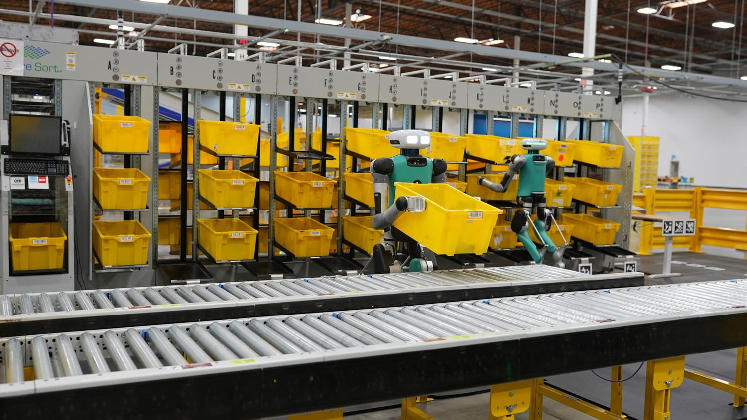
Puh - so many details here - a highlevel suggestion - let's just buy Agility Robotics, looks like they already built exactly what Tesla needs for the start:

 www.agilityrobotics.com
Is anyone suprised they left stealh mode right after AI day to position themselves for Tesla to be aquired?
I mean - we can replace that LIDAR thing on the top with Tesla Vision, paint the robot in black/white and we're done right?
Agility Robotics
Providing advanced automation solutions for supply chain and manufacturing.
www.agilityrobotics.com
Is anyone suprised they left stealh mode right after AI day to position themselves for Tesla to be aquired?
I mean - we can replace that LIDAR thing on the top with Tesla Vision, paint the robot in black/white and we're done right?
2
22522
Guest
There are several reasons:Why wouldn't each tendon have it's own actuator? A general purpose AI bot would need fidelity and dexterity in it's fingers to do any task a human can do, such as cooking or fine detail construction like installing bolts or such, right?
- Each joint that moves ends up needing an actuator. This ends up being a lot of actuators. Then the forearm get crowded. If they have only "control actuators" vs "power actuators" maybe things will fit better.
- Routers have a lot of power, but they spin at 5,000 rpm. To make a finger move they need a lot of gear reduction. Gear reduction systems can fail and are expensive. The more gear reduction systems you have the worse it is. Smaller ones require more precision.
So yes, this approach is challenged on dexterity, but has a good chance cost and reliability, if the dexterity is solved. Trying to find minimum parts count.
Thank you keeping the dexterity goal front and center.
2
22522
Guest
This is a request to make the lower forearm spin like a drill without the need for re-grasping when rotary motion is required. The time savings can be an order of magnitude. This slide shows how operating to reduce re-grasp time, when it is required, must be deliberate. This case is about a dedicated tool to speed hydraulic hose changes on mountain bikes. Don't know if there is anything like this in space.
Summary: Regrasps are slow. Things will be faster if regrasps are not needed.
Having an option where the lower arm can spin with no limit on number of rotations can be faster.

Summary: Regrasps are slow. Things will be faster if regrasps are not needed.
Having an option where the lower arm can spin with no limit on number of rotations can be faster.
2
22522
Guest
This link has the joint geometry needed to calculate the tension in a tendon.
 courses.lumenlearning.com
They do math that says a bicep tendons sees 7 times the load supported. If you can curl 30 lbs, that muscle is pulling/supporting about 200 lbs.
My forearm muscle group is about the size of my biceps. So if it is all one motor it needs to produce 200 lbs of tension in the tendon set. And a ratchet that holds that tension with no current draw would be good. So that is a starting place. There is some psi number a magnetic gap will support - like 10 psi or something. So if that is true the surface area of the drum wants to be 20 square inches.
If the radius is 1 inch the perimeter line length is 2(3.14159)(1), or 6 inches. So a 2 inch diameter cylinder that is 3 inches long will provide about 180 lbs of tendon force. Should be ok for this robot. So there in no need or any gear reduction. If there is no mistake here. Need to be a bit more thorough.
Forces and Torques in Muscles and Joints | Physics
Study Guides for thousands of courses. Instant access to better grades!
They do math that says a bicep tendons sees 7 times the load supported. If you can curl 30 lbs, that muscle is pulling/supporting about 200 lbs.
My forearm muscle group is about the size of my biceps. So if it is all one motor it needs to produce 200 lbs of tension in the tendon set. And a ratchet that holds that tension with no current draw would be good. So that is a starting place. There is some psi number a magnetic gap will support - like 10 psi or something. So if that is true the surface area of the drum wants to be 20 square inches.
If the radius is 1 inch the perimeter line length is 2(3.14159)(1), or 6 inches. So a 2 inch diameter cylinder that is 3 inches long will provide about 180 lbs of tendon force. Should be ok for this robot. So there in no need or any gear reduction. If there is no mistake here. Need to be a bit more thorough.
Similar threads
- Replies
- 0
- Views
- 134
- Replies
- 16
- Views
- 474
- Replies
- 4
- Views
- 383
- Replies
- 1
- Views
- 734