Welcome to Tesla Motors Club
Discuss Tesla's Model S, Model 3, Model X, Model Y, Cybertruck, Roadster and More.
Register

Tesla inverter DC wiring

This site may earn commission on affiliate links.
I have a question regarding how DC connections are established on the new Tesla branded inverter.

I have a 21KWhr solar roof with several powerwalls and three 7.6Kw inverters.

Shortly after installation I noticed that one of the three Tesla inverters seemed to take a very long time (hours) to come online. Often it would not come online at all and would continuously cycle through self test. Tesla dispatched a couple of guys and they doubled up the wiring connections on the inverter. Or to put it another way DC comes into the lower terminals and they installed jumpers connecting terminals one and three, and two and four so DC power enters the inverter on four inputs. Yes if I look at the inverter through the web browser it shows power on all four inputs even though there are only two strings coming in.

My question is does this scheme lower the amount of power that is converted to AC or does it not make a difference? The reason I am asking is that I used to get 17.5 to 18.00 kW on the entire system mid day and now I am only getting 15kW, Nothing has changed except this wiring modification.

Any electrical engineers out there that can explain this? Also why changing to this wiring method did the original problem go away? Now it comes online in a few minutes after completing self test.

Thank you
IMG_2592.JPG
 
The reason I am asking is that I used to get 17.5 to 18.00 kW on the entire system mid day and now I am only getting 15kW, Nothing has changed except this wiring modification.

Are you sure that the difference in max production during the middle of the day is not just "the sun is at a slightly different angle right now, than it was 2 weeks ago"?

I only mention that because, for example, my peak numbers (both instant, and daily) are lower, as expected, because the sun is at a slightly different angle. I am not saying that is it, but wanted to bring it up as a "occams razor" point on why you might see lower peak generation right now vs whenever you used to get 17.5-18.0.
 
I have a question regarding how DC connections are established on the new Tesla branded inverter.

I have a 21KWhr solar roof with several powerwalls and three 7.6Kw inverters.

Shortly after installation I noticed that one of the three Tesla inverters seemed to take a very long time (hours) to come online. Often it would not come online at all and would continuously cycle through self test. Tesla dispatched a couple of guys and they doubled up the wiring connections on the inverter. Or to put it another way DC comes into the lower terminals and they installed jumpers connecting terminals one and three, and two and four so DC power enters the inverter on four inputs. Yes if I look at the inverter through the web browser it shows power on all four inputs even though there are only two strings coming in.

My question is does this scheme lower the amount of power that is converted to AC or does it not make a difference? The reason I am asking is that I used to get 17.5 to 18.00 kW on the entire system mid day and now I am only getting 15kW, Nothing has changed except this wiring modification.

Any electrical engineers out there that can explain this? Also why changing to this wiring method did the original problem go away? Now it comes online in a few minutes after completing self test.

Thank youView attachment 703240
This does not lower what the inverter can produce. If anything it increase the peak capacity available because you have two channels worth of input capacity so it is less likely to clip (limit production because of inverter capacity)

Most likely you are seeing less production because of soiling (your panels are dirtier), weather and the sun changing angles (because everyday it is slightly different).
 
Hi,

brand new owner of Tesla inverter as well. I got 3 strings coming off the roof and electrician jumped one string like shown here as well. Any idea why they jump the strings?

Thanks
Assuming you mean paralleling multiple inputs on the inverter, the answer is more capacity. Each input has certain capacity, if you put two together in parallel then you have double the capacity.

The panels potentially could have been wired as two separate arrays instead. If they are unshaded and all oriented the same way there is practically no need. The potential benefit (to the installer) of a single array is cheaper/faster/less wiring. A single higher voltage string might be better than two shorter strings because you can hit the minimum voltage sooner and later (tiny gains). There are benefits to having them as separate arrays like debugging or better performance is there is some shading.

I have 4 arrays on the roof facing 3 directions (6 + 5 + 3 panels). So I get why they did 3 strings. I am just not sure why they decided to parallel one of them and the others not.

When checking installer access on TEG, I see the individual string readings and surprisingly it is the middle performing:
String 1: 68 V / 1.6 A
String 2: 191 V / 8 A
String 3: 97 V / 2.3 A
String 4: 97 V / 2.2 A

The reading confirms that inputs 3 & 4 were paralleled because it shows the same string data. So if I understand you right, input 3 + 4 is likely the string from biggest array (6 panels) and was paralleled on inverter to make its life easier?

Thanks
Each panel should be about 32V when completely unshaded assuming these are the 340W panels. Was there a lot of shading at the time you took the data? String 2 looks to be 6 panels but hard to tell the rest.
 
Each panel should be about 32V when completely unshaded assuming these are the 340W panels. Was there a lot of shading at the time you took the data? String 2 looks to be 6 panels but hard to tell the rest.
yeah, panels pretty much unshaded. 6 facing south-east, 5 facing north-east, 3 facing south-west. the NE ones will have very little sun at this time because the sun stands a little low in November.

I am about to shade some panels to get an idea which string is which array :)
 
yeah, panels pretty much unshaded. 6 facing south-east, 5 facing north-east, 3 facing south-west. the NE ones will have very little sun at this time because the sun stands a little low in November.

I am about to shade some panels to get an idea which string is which array :)
The current will be proportional to illumination so given that info String 1 is probably the NE 5 panel array and String 3/4 is the 3 panel SW array.

It's a little strange that you are only getting 68V on string 1 unless it was a typo.

You can look again right after sunset when all the panels should be equally illuminated with diffuse light. At that time you should read pretty close to 32V per panel.
 
well ... the 5 panels NE is 2 arrays (2 + 3 panels). I think they gave the 2 panels a string, have the 6 SE on a string and connected the 3 NE + 3 SW into a string of 6 ... that would make sense from the voltage reading. So maybe they put the 3 NE + 3 SW on one string and paralleled it on input 3 + 4. I will need to monitor that a little more...
 
well ... the 5 panels NE is 2 arrays (2 + 3 panels). I think they gave the 2 panels a string, have the 6 SE on a string and connected the 3 NE + 3 SW into a string of 6 ... that would make sense from the voltage reading. So maybe they put the 3 NE + 3 SW on one string and paralleled it on input 3 + 4. I will need to monitor that a little more...
That would be a strange choice as generally you wouldn't want panels facing different directions on the same string but I wouldn't put it past them. Do you have a copy of the plans from Tesla? It should show how it was intended to be wired. If not you can request it.
 
Tesla did installation inspection today and confirmed my assumption.

In order to parallel panels, they must be the same size, so they couldn't parallel 2+3 NE facing. Instead they chose to parallel 3 NE + 3 NW (stupid) instead of just running a fourth string. So now I am loosing out on those two arrays (maybe about 30-50%?).

If Tesla would provide design details and permit paperwork to home owner upfront, then I would have most likely caught that before it was an issue :(

Regarding the original on topic question:
In my case, the jumper on the inputs on the inverter is done for that string that also has paralleled wiring for the panels on the roof.
You aren't losing much as long as shading aren't a big issue


Attachments

  • SE_TA_Efficient_East_West_orientated_PV_systems_with_one_MPP_Tracker_EN (1).pdf
    352.8 KB · Views: 99
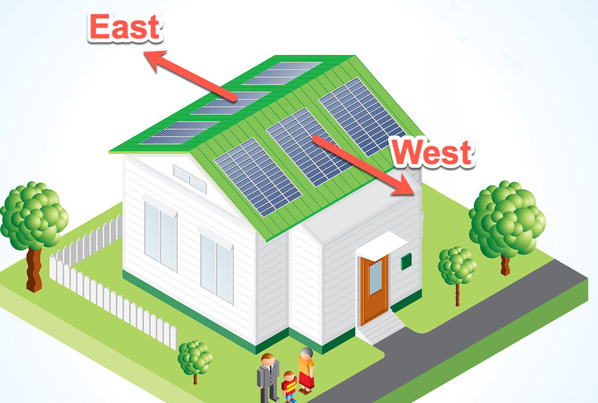
my roof is 30% tilt. and since it is NE and NW, they are only 90° opposite, not 180°. The report says it can work but it would have been just so much better if they put it on a fourth string. The inverter supports it after all, so they just skimped on wiring and a bigger conduit.

I am fairly sure they are pulling some sort of shenanigans in their inverter since it is not connected to the regular inputs but jumped and put into a different connector underneath. I was not able to find any details on the Tesla inverter to understand what this does for them. only thing I found was this https://www.tesla.com/sites/default...erter_and_solar_shutdown_device_datasheet.pdf which shows that the 7.6kW model has 4 mppt (we know) and they can do 1-2-1-2 ...whatever that means and does. I assume the 2's stand for jumped inputs like we observed in our installations.

I had to dig a little to understand that the parallel array shouldn't affect each other too much but there will definitely be a loss also since the arrays are opposite shaded in my situation.
Jumpered mppt is normal for parallel strings. But parallel strings normally should face same direction.
 
Well I heard back from Tesla Energy regarding the jumpers. For those that have lost track I started this thread a few months back wondering why the jumpers were installed on my Tesla Inverters as shown in the attached photo above. I was also curious as to why my production dropped nearly 60%.

Turns out that the jumpers are not a best practice with solar roofs. They are permitted and common with solar panels. A crew is coming out to remove the jumpers and rewire it. I am assuming they will put it back the way that it was.

Stay tuned.
 
  • Like
Reactions: BGbreeder