Welcome to Tesla Motors Club
Discuss Tesla's Model S, Model 3, Model X, Model Y, Cybertruck, Roadster and More.
Register

Tesla Virtual Power Plant in CA

This site may earn commission on affiliate links.
If you log into the web portal of the Tesla gateway and click summary it's the last line. I don't know if it's in the app anywhere. I have 2xPW and my site export limit is set to 8kW. So if I have export all enabled and it's peak pricing the gateway will send all solar to the grid and make up the rest up to 8kW, while still providing for the home load as well. As the sun gets lower the amount of draw from he PWs goes up. I don't know where/who set the limit originally and it does not appear to be user configurable.
That is interesting.. I'm on PG&E NEM2MT and my interconnection agreement says:
2.7.3 Total maximum level of power that may be exported by the Generating Facility: 26.025 kW

However, the "site limit export" from the summary says 10.77 kW (I have 3 PW2).
 
Does anyone know if the Site Export Limit will affect VPP like it does for "export all"?
Yes, Site export limit will not allow more than the stated combined PV and PW to backfeed to the panel and grid pas the marked CT (usually inside/between the TEG and the breaker connecting it to the main panel. This is usually done instead of a main panel upgrade, to keep within the limits set by NEC 705.12.
 
That is interesting.. I'm on PG&E NEM2MT and my interconnection agreement says:
2.7.3 Total maximum level of power that may be exported by the Generating Facility: 26.025 kW

However, the "site limit export" from the summary says 10.77 kW (I have 3 PW2).
Site import limit is different than export limit.

This heavily depends on your installation design but Site Import limits are generally set to prevent tripping of the breaker feeding the TEG, when there may be too many loads on the backup side to really be served 100% of the time by the breaker feeding the TEG. There are also other uses for it. What does your electrical diagram look like?

This setting will deploy Powerwall power if possible to serve some of those loads which otherwise might have been too much for the breaker from the grid source.
Are you saying that my interconnection agreement is what PG&E would allow to be exported, but my install / design might say a lower limit is supported by equipment on my side?

Here's my single line diagram
1658323533287.png
 
Are you saying that my interconnection agreement is what PG&E would allow to be exported, but my install / design might say a lower limit is supported by equipment on my side?

Here's my single line diagram
View attachment 830577
Yes, there may be 2 different limits here.

Unfortunately, the plans do not show the CT's in great detail. However there are some (maybe 2 sets?) shown between the TEG and the subfeed lugs in the MSP. If I was backfeeding into this service panel under the 120% rule, I would ensure that no more than 70A of onsite generation would backfeed to the service panel at any given time. So likely that is what your export control is doing, protecting the MSP bus. Looking at your diagram it looks like you still have loads remaining in your service panel. so this is appropriate. If you had a whole home backup or only 25A worth of breakers remained in the MSP, you could be compliant with the spirit of the 100% rule instead.

I do not understand why there is not a 200A main breaker in your "New Subpanel #2." Since this panel is exposed to 200A worth of grid power and all the on site generation as well. It could be that this limit is also electronically controlled with PCS settings and panel limits but it is not spelled out explicitly in these plans.
There are no loads remaining in the Service Panel. The only thing there is the Sub Feed Lugs.
I also confirmed visually that there is no main breaker in "New Subpanel #2".

Is "New Subpanel #2" considered exposed to 200A of grid power if the TEG is between the service panel and "New Subpanel #2"?
I considered the TEG to be the hub since all three things are tied into it: Grid Power, Load Panel, "New Subpanel #2".

Anyway just wanted to clarify that my setup is considered whole home backup because there are no loads in the Service Panel.
The Lumin Smart Panel was installed to make sure that the circuit for my largest AC is not available if Grid power is offline.
I insisted on this instead of partial home backup because I'm confident when I replace with Heat pumps, the rating will be supported by 3 PW2.
 
  • Like
Reactions: Vines
Yes, "New Subpanel #2" needs to have a main breaker. As currently configured, its bus, and the 3/0 copper feeder supplying it, could be overloaded.

If per chance the sum of the breakers (per leg) does not exceed the subpanel busbar rating of 225A, the NEC would recognize that as protecting the busbar, but not as protecting the 3/0 copper feeder supplying it.

Cheers, Wayne
 
  • Like
  • Informative
Reactions: BGbreeder and Vines
There are no loads remaining in the Service Panel. The only thing there is the Sub Feed Lugs.
I also confirmed visually that there is no main breaker in "New Subpanel #2".

Is "New Subpanel #2" considered exposed to 200A of grid power if the TEG is between the service panel and "New Subpanel #2"?
I considered the TEG to be the hub since all three things are tied into it: Grid Power, Load Panel, "New Subpanel #2".

Anyway just wanted to clarify that my setup is considered whole home backup because there are no loads in the Service Panel.
The Lumin Smart Panel was installed to make sure that the circuit for my largest AC is not available if Grid power is offline.
I insisted on this instead of partial home backup because I'm confident when I replace with Heat pumps, the rating will be supported by 3 PW2.
If there are no loads in the MSP, then I do not understand why export limit is set. That does not mean it is not appropriate to have a limit, and I cant really say it is set without more information

Where in your system do you see CTs and labels that say something like:
WARNING: THIS SENSOR IS PART OF POWER CONTROL SYSTEM. DO NOT REMOVE. REPLACE ONLY WITH SAME TYPE AND RATING
and
PCS CONTROLLED CURRENT SETTING____A
THE MAXIMUM OUTPUT CURRENT FROM THIS SYSTEM TOWARDS THE MAIN PANEL IS CONTROLLED ELECTRONICALLY. REFER TO MANUFACTURERS INSTRUCTIONS FOR MORE INFORMATION

Could you label the location in the diagram where those CT's which control a Power Control System (PCS) might be installed?
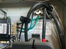
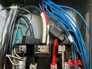
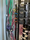
These are the only locations I found with CT (or CTish) items.

The picture with two CTs is the top of the TEG on the copper coming from the Service Panel

The picture with the yellow, blue, orange wire tape are the three circuits of PV in the Generation Panel

The last picture is the top of the "New Subpanel #2" which contains all my loads.
(This one is tapped into the wire I just can't remember why they did it.)
 

Attachments

  • IMG_7459.jpg
    IMG_7459.jpg
    574.3 KB · Views: 40
  • IMG_7460.jpg
    IMG_7460.jpg
    627.8 KB · Views: 34
  • IMG_7461.jpg
    IMG_7461.jpg
    556.5 KB · Views: 32
These are the only locations I found with CT (or CTish) items.

The picture with two CTs is the top of the TEG on the copper coming from the Service Panel

The picture with the yellow, blue, orange wire tape are the three circuits of PV in the Generation Panel

The last picture is the top of the "New Subpanel #2" which contains all my loads.
(This one is tapped into the wire I just can't remember why they did it.)
Picture 7459 appears to be inside the GW1? Looks like an insulation piercing connector, typically designed for line and load side taps. I have no idea what is happening there, and I do not see a tap on the L2 conductor. I guess someone needed 120V inside there?
#7461 shows the PV circuits being captured by the TEG inside another subpanel, and also the CTs for the other monitoring system.
#7460 shows the CT's capturing the backed up loads.

Honestly, it would help if you got better answers from your installer because I can only guess based on limited information. I do not know the limitations of a GW1 with regards to PCS settings. I do not know that the GW1 is listed under UL 1741 for PCS, and do not understand why the export limit is set either.
I appreciate you taking the time to respond. I don't think I care enough to pursue it further.
I don't have the "Export All" option and probably wouldn't use it even if I did. If I'm limited during VPP then I'm limited.
One day this week I used all the way down to 8% during peak (reserve set at 10%). Highs of 108 require a lot of AC.
You are welcome.
I would recommend getting a main breaker installed per code if nothing else.
 
  • Like
Reactions: BGbreeder
I kept on getting rejected for the VPP despite enrolling from Ohmconnect a couple weeks ago. Took about 3 weeks, but they've finally unenrolled me and was able to join. Have there been any events recently? It's been well over 100 for about two weeks here.
 
I’ve been looking at the CAISO charts on these hot days and seems like there is plenty of capacity, so I guess the event isn’t needed. The forecasts are usually pretty accurate, so unless there is a huge spike seems like the events will only happen to test something out.

 
  • Like
Reactions: bmah
I’ve been looking at the CAISO charts on these hot days and seems like there is plenty of capacity, so I guess the event isn’t needed. The forecasts are usually pretty accurate, so unless there is a huge spike seems like the events will only happen to test something out.

A significant transmission or generation forced outage would also be a reason for calling on VPP energy.
 
  • Like
Reactions: dailo
I recently had a 17kwh system installed in Northern California. This morning I received an option to sign up for Tesla virtual Power plant.
Without any context for this proposal, I did not proceed. Has anybody signed up for this and has received money from Tesla? What impact does this have to your sellback to PG&E to off-set your other costs?


Thanks
In addition to your 17 kW (not kWh) panels you must also have Powerwalls as these are needed to be part of the VPP. The $2.00/kWh that is paid for VPP participants is in addition to the standard NEM 2.0 credit for your exports, so there is no downside other than if there is an outage right after the event your Powerwalls won't be at full charge and maybe some very slight additional wear on your Powerwalls. The wear is likely to be very minimal to none as the there is a maximum of 20 events per year as part of the program and since most performance loss for LION batteries is when they are held at 100% charge this would lower the charge level and help.

People that were part of the beta program last year did get a check, but no one in the current program would have received any compensation as the payment will be on annual basis and the first year is not complete nor have there been any events yet.

Personally I have my Powerwalls set to a reserve level 75% to discharge through Peak and when notified of a VPP event I will change the level down to 10% to maximize my exports for the event. The risk of an outage happening right after a VPP event is low IMHO.
 
  • Informative
Reactions: Nosken
In addition to your 17 kW (not kWh) panels you must also have Powerwalls as these are needed to be part of the VPP. The $2.00/kWh that is paid for VPP participants is in addition to the standard NEM 2.0 credit for your exports, so there is no downside other than if there is an outage right after the event your Powerwalls won't be at full charge and maybe some very slight additional wear on your Powerwalls. The wear is likely to be very minimal to none as the there is a maximum of 20 events per year as part of the program and since most performance loss for LION batteries is when they are held at 100% charge this would lower the charge level and help.

People that were part of the beta program last year did get a check, but no one in the current program would have received any compensation as the payment will be on annual basis and the first year is not complete nor have there been any events yet.

Personally I have my Powerwalls set to a reserve level 75% to discharge through Peak and when notified of a VPP event I will change the level down to 10% to maximize my exports for the event. The risk of an outage happening right after a VPP event is low IMHO.
I have a 12.5 kW micro inverter system and am looking at 1 Powerwall or another brand (we rarely have outages) to arbitrage my NEM 1.
Would installing any battery and activating VPP knock me out of NEM1?
Could I install the Tesla Powerwall to my Enphase Micro inverter system?
Thanks for any info and input!