


Welcome to Tesla Motors Club
Discuss Tesla's Model S, Model 3, Model X, Model Y, Cybertruck, Roadster and More.
Register
Install the app
How to install the app on iOS
You can install our site as a web app on your iOS device by utilizing the Add to Home Screen feature in Safari. Please see this thread for more details on this.
Note: This feature may not be available in some browsers.
-
Want to remove ads? Register an account and login to see fewer ads, and become a Supporting Member to remove almost all ads.
You are using an out of date browser. It may not display this or other websites correctly.
You should upgrade or use an alternative browser.
You should upgrade or use an alternative browser.
Think I need a new PEM Fan... Anything else to check?
- Thread starter gregd
- Start date
Um, how can I get to it?You could check the voltage at the PEM connector-that wouldn't require anything under the car.
Short update...
I had a great chat with Peter at Gruber. HIGHLY recommend these guys. The question was whether I'd missed anything in my analysis, and to get pointers on the replacement of the fan motor assembly.
I sent him the logs from the car, which he received in a few moments (n.b. I still can't upload them to Tesla). He is developing a better decoder than the one currently available. It's not ready for release yet, but it determined that my PEM was putting out about 12v on both the PEM and Motor fan pins at the time of the failure, and both lines went slack (zero current) at the same time. Since the power to the motor comes from the two independent pins on the connector, and are wired together externally on their way to the fan motor, for the current to go to zero simultaneously means that the issue is highly unlikely to be the fan connector at the PEM. Either the wiring has broken between where the two lines are tied together and the motor, or the motor itself has failed.
We decided the next test would be to get a set of ramps and get under the car to access the wiring from there. Try disconnecting the fan and supplying it with 12v and see if it spins. Also measure the voltage out from the PEM and confirm that it is supplying the 12v expected as was suggested here earlier.
They have the fan assembly in stock, so it shouldn't be too hard to get it, if that's the issue. He confirmed the loosening of the sway bar, and said the rest of the exchange should be fairly routine. I'll head out to the car parts store early next week for the ramps. In the mean time, I can get about 8 minutes charging at 240v / 15a, using a shop vac to blow air into the side of the driver-side blower before OVMS reports the PEM crossing 50C.

The plot thickens... TL;DR: It's not the fan motor. Now what?
Got the car up on ramps, and the cover removed from below. Connectors un-hooked. Put 12v on the motor and it spins up just fine. Meter on the PEM-side shows 12-ish volts coming out from both (towards the original motor fan and PEM fan). The two voltages are slightly different, as one would expect from separate drivers aimed at separate blowers. Put the connectors back on, and nothing happens.
Since the two connectors on the blower side are wired together, I plugged the PEM-side in and measured the Motor-side, so I should be able to see what the PEM is feeding the blower when it's connected, and the reading was less than a volt.
The only thing I can think of is a high resistance between both connectors and the PEM drivers, so the meter reads voltage, but perhaps there is not the ability to deliver any current. That means that both pins on the PEM had to have failed at the same time, which is not likely.
What else could it be?
Some kind of failure in the driver(s) such that it (they) can deliver 12V unloaded but not under load?What else could it be?
Hope not. That would be a new PEM...Some kind of failure in the driver(s) such that it (they) can deliver 12V unloaded but not under load?
I tried hooking a 6W tail light bulb to the driving side of the connector, and neither side had enough oomph to even get a glow from it.
Good news is that a Power Pole connector kind of fits over the blower side of the connector (essentially a pair of F-type blades), so it was easy to run the fan from a battery while daily charging, but man this thing draws a lot of power. 12 ga wire got quite warm, but didn't blow the 25A fuses that I have in line with the battery... I briefly thought the issue might be the PEM going into an over-current shutdown (motor functional but drawing too much), but given the lamp test failure, that can't be it.
And yet, the PEM output measures 12V unloaded?I tried hooking a 6W tail light bulb to the driving side of the connector, and neither side had enough oomph to even get a glow from it.
Yep. I may try an even lower wattage bulb, perhaps an old 12v panel lamp if I can find one in the junk box. At some point, it's got to work.And yet, the PEM output measures 12V unloaded?
The only scenario I can think of that might explain the evidence is that both contacts have, in fact, burned on the underside of the PEM. One mostly went earlier, but since the other side was still working, it carried most of the load. So the PEM didn't object to either one; current flowed. Then the second side went, effectively transferring the load to the first, which failed completely. Both contacts therefore appeared to fail within the same polling time, so they were reported with the same time stamp. Resolution is 1 second, apparently.
Given that I went 9 rounds with the SC team last Fall about that connector, and they pronounced it perfectly good, I'm going to be "severely disappointed" that it has now failed so soon. And if its failure took out other stuff, like the PEM, I'll be doubly "disappointed".
It really helps to remember Ohm’s Law when diagnosing with a multimeter. Just because you measure 12 volts with the meter does not mean that you will have enough current to drive a motor (or lamp). If the connection has an impedance of 120 ohms you could only push .1 amps through it. Measuring 1 volt at one side of the motor tells me that 11 volts are lost across a resistance. This of course assumes I understand how you placed the meter leads and that the PEM was trying to drive the motor. Many people have reported the fan connector problem and many times it is reported just after a visit to the service center. Myself included. Just because a technician said the connector looked fine (to them) doesn’t really mean much. If the motor is OK then the next most likely culprit is the connector under the PEM. It would be a shame to spend thousands on a rebuilt PEM if it is just the connector.
Yes, quite familiar with Ohm and his friends. I specifically challenged Tesla on the connector last Fall, and I am just reporting what they claim. There was a visual inspection, as well as a "pull test" to verify the pins were properly mating. I do suspect the connector, especially given the current this thing draws at maximum. Do you (anyone?) know what the actual draw should be at 12v, if that's what the PEM is trying to push into it?It really helps to remember Ohm’s Law when diagnosing with a multimeter. Just because you measure 12 volts with the meter does not mean that you will have enough current to drive a motor (or lamp). If the connection has an impedance of 120 ohms you could only push .1 amps through it. Measuring 1 volt at one side of the motor tells me that 11 volts are lost across a resistance. This of course assumes I understand how you placed the meter leads and that the PEM was trying to drive the motor. Many people have reported the fan connector problem and many times it is reported just after a visit to the service center. Myself included. Just because a technician said the connector looked fine (to them) doesn’t really mean much. If the motor is OK then the next most likely culprit is the connector under the PEM. It would be a shame to spend thousands on a rebuilt PEM if it is just the connector.
Yeah, this is what I was thinking. I'd strongly prefer not messing with (unhooking) the HV wiring. Is there enough slack that I can unbolt the PEM and raise it up on the passenger side? I think there just the big bolts in the back (one on each end) and the two smaller screws on each tab. Anything else?You need to look at the connector. Unbolt the PEM and raise it up, or take out the wheel well liner to get at the connector.
I've not looked at the wheel well liner. How is that removed? That might be a lot easier, but I cannot remove the wheel if that's required too. Maybe the trunk tub instead?
Greg
Another update, and a puzzle. Any guidance appreciated!
Electrically this isn't making sense; I think there is something else going on here.
Looking at the log decode I got from Gruber, I see that the two fan driver outputs are tracking exactly (within 0.01v) to the same value. That means that both sides are tied together, which is what we expect. I have confirmed that the blower motor side of the wiring is as expected. Both the positive and negative feeds are tied together at the motor. That also mean that both sets of pins at the PEM connector are making contact, at least superficially. So far, so good.
I took a few measurements with both connectors disconnected at the motor, so I can independently measure the voltage output from the PEM. Both show about 13.4v when I wake the car up, and more significantly, both are exactly the same. I.e. if I measure the difference between the two positive leads, I get zero volts. It's impossible for the two drivers to be supplying exactly the same voltage, so I conclude that they must be tied together somewhere upstream, between the PEM and the connectors at the blower motor. And, in fact, they measure zero ohms between them. There is a small difference between the two negative pins (a few mv), which changes over time. So, these are clearly not tied together. It also means that the two negative sides are not connected together inside the PEM, and that neither negative side are connected to chassis ground (as measured to the bolt holding the sway bar). They are floating.
That makes the shunt across the positive leads a puzzle. Why is it there? It cannot be of any benefit, given that the two supplies appear to be floating, except that the two supplies are tied together at the motor. There does appear to be some semiconductoring between the negative leads and chassis ground - a few k ohms in one direction, a few meg in the other. Not sure what to make of this, as I don't have access to the PEM schematics.
Towards a permanent fix, and assuming the connectors at the PEM are toast, simply replacing the connectors only kicks the proverbial can down the road. Should one tie the two supplies positive leads together inside the PEM, so that the pins share the load regardless of whether the PEM or Motor side is driving more intensely? Is this this "load sharing" even considered proper engineering practice when only 2 pins are involved? What about the negative side? I note that I have never seen a Internet posting of the negative pins burning, only the positive ones. Odd.
So, outstanding questions:
1. What is the proper draw from the blower motor at full power? Through a long cord (to introduce some resistance), I see it drawing about 8.6 amps at 7.8 volts. I can't currently measure it at full power, as I don't want to jeopardize my meter. The implication here: if the motor is drawing excessive power, did it cause the connector to fail and should also be replaced?
2. What is with the shunt between the two positive leads? Has anyone seen this on other cars? Is there perhaps another connector somewhere behind the blower bulkhead that might be where the fault is?
3. Can the PEM cover be removed (to access the board with the bad connector on it) without removing the entire PEM from the car? I see a number of screws on top that might be accessible. Any others? (Anybody have a sonic screwdriver I can borrow...?)
4. Is there enough slack in the wiring to the PEM to lift up the passenger end, to access the connector and wire harness?
Thanks!
Greg
so when you charge you don't hear the fans underneath the pem or the rear of the car turn on? you just mentioned "when you wake the car up" this means the car is going to sleep and battery / pem is achieving temperature to state of idle.
Do you have ovms? is your pem still reaching 62c? and what about battery temps?
When you wake the car up there is also a Fan inside the PEM you should hear as well; like a pcboard fan - do you hear this along with the coolant pump running? you can even feel the pem vibrating from the pcboard fan.
.jpg")
Do you have ovms? is your pem still reaching 62c? and what about battery temps?
When you wake the car up there is also a Fan inside the PEM you should hear as well; like a pcboard fan - do you hear this along with the coolant pump running? you can even feel the pem vibrating from the pcboard fan.
Last edited:
Hi Jason,so when you charge you don't hear the fans underneath the pem or the rear of the car turn on? you just mentioned "when you wake the car up" this means the car is going to sleep and battery / pem is achieving temperature to state of idle.
Do you have ovms? is your pem still reaching 62c? and what about battery temps?
When you wake the car up there is also a Fan inside the PEM you should hear as well; like a pcboard fan - do you hear this along with the coolant pump running? you can even feel the pem vibrating from the pcboard fan.
View attachment 559817
Per my updates above, the PEM itself seems fine, and the blower motor, powered locally, is also fine. The issue is in the wiring and/or connectors in between. If I were to charge the car without supplying air somehow, it would surely overtemp and be unhappy. I've not done that. For a while I was using my ShopVac to blow air into the side of the blower under the car, most of which exited out the other side. But it slowed the rise in heat to the point where I could accomplish the daily top-off in one or two sessions. Now, with the car up on ramps and the underside exposed, I can power the blower separate from the car, and cool it that way for charging.
But the problem of where the issue in the wiring is still exists. I'm trying to do as little disassembly as I can, over risk in breaking something and to keep the car in a chargeable state, and using a test-and-noodle approach to figure out what is going on. That was the subject of my last update, and the questions at the end.
Yes, you could reach the board mounted connector that way but you can’t get the connector or the board out because it is screwed to the PEM from the bottom.3. Can the PEM cover be removed (to access the board with the bad connector on it) without removing the entire PEM from the car? I see a number of screws on top that might be accessible.
1. What is the proper draw from the blower motor at full power? Through a long cord (to introduce some resistance), I see it drawing about 8.6 amps at 7.8 volts. I can't currently measure it at full power, as I don't want to jeopardize my meter. The implication here: if the motor is drawing excessive power, did it cause the connector to fail and should also be replaced?
according to the spec sheet maximum current is 28A. Depends on static pressure.
ML Auto
Member
It sounds like the PEM controls the ground to operate the fan, not the positive. Your voltage reading upon wakeup would comfirm this, unless the PEM is already hot and calling for the fan to operate. That and the grounds should be connected to ground at all times if the positive was controlled. Both positives would be connected to the APS output inside the PEM, and have exactly the same voltage. The original dual motor setup used two separate circuits, which are now operated at the same time, and connected to the same terminal on the single fan motor. Apparently the single motor used less current than the total of the two original motors, so connector life is increased. If I remenber correctly the CFM of the single motor is less than that of the total of the dual motor setup, so the only reason for the "update" would be to prevent the connector form burning up. You need to check the connector.
You can raise the PEM up enough to get at the connector, but you will need to disconnect the three orange motor leads on the PEM thru the access panel in the trunk. They do not have any power unless you are trying to move the car, so just make sure the key is off.
You can get the wheel well liner off by working around the wheel, but it is a lot easier with the wheel removed.
I used some 30A anderson conectors with a pigtail soldered direclty to the PEM terminals, and permently fixed the issue.
Thanks for this! I was thinking PowerPoles too, though they're not especially weather or vibration proof. How well do they hold up?It sounds like the PEM controls the ground to operate the fan, not the positive. Your voltage reading upon wakeup would comfirm this, unless the PEM is already hot and calling for the fan to operate. That and the grounds should be connected to ground at all times if the positive was controlled. Both positives would be connected to the APS output inside the PEM, and have exactly the same voltage. The original dual motor setup used two separate circuits, which are now operated at the same time, and connected to the same terminal on the single fan motor. Apparently the single motor used less current than the total of the two original motors, so connector life is increased. If I remenber correctly the CFM of the single motor is less than that of the total of the dual motor setup, so the only reason for the "update" would be to prevent the connector form burning up. You need to check the connector.
You can raise the PEM up enough to get at the connector, but you will need to disconnect the three orange motor leads on the PEM thru the access panel in the trunk. They do not have any power unless you are trying to move the car, so just make sure the key is off.
You can get the wheel well liner off by working around the wheel, but it is a lot easier with the wheel removed.
I used some 30A anderson conectors with a pigtail soldered direclty to the PEM terminals, and permently fixed the issue.
The data on wake up with a cold PEM and traction motor (24C) still shows +13.4v being sourced by the PEM. I don't know from which side (PEM fan or Motor fan), given the bridge between the two sides, but it's clearly trying to spin the fan even when cold. Given that the difference in the negative side is only a few mv, it seems like it's both sides that are being so driven. This was a bit of a surprise. I wonder if it's because of the prior 1144 / 1146 alerts.
To solder on a pigtail, I presume I would need to remove the entire PEM from the car in order to get at the screws on the bottom. Or, with the 3 motor wires removed, will the PEM "flip up" on its two main supports in the back (towards the front of the car) if I just undo the 3 screws at each end? It almost seems like it was intended to do this.
Alternatively to making a pigtail, a thought... Presuming that the PEM connector itself has been damaged along with the cable going to the fan motor, would replacing the connector with a stock unit AND bridging the two positive pins together inside the PEM make it robust enough to be used normally? I'm a bit puzzled that all the pictures of damaged connectors seem to be on the positive pins only. Electrically I don't understand this, but if that's "expected", would bridging them inside the PEM be the proper way to prevent the failure from recurring? Keeping the PEM looking "normal" would prevent Tesla from refusing to work on the car.
Can the car be charged with the 3 motor wires removed, but everything else connected? I thought the motor was part of the charging circuit, or was that only on the 1.5's?
Sorry for all the questions, and thanks for your help!
Greg
Thanks for this! I was thinking PowerPoles too, though they're not especially weather or vibration proof. How well do they hold up?
The data on wake up with a cold PEM and traction motor (24C) still shows +13.4v being sourced by the PEM. I don't know from which side (PEM fan or Motor fan), given the bridge between the two sides, but it's clearly trying to spin the fan even when cold. Given that the difference in the negative side is only a few mv, it seems like it's both sides that are being so driven. This was a bit of a surprise. I wonder if it's because of the prior 1144 / 1146 alerts.
To solder on a pigtail, I presume I would need to remove the entire PEM from the car in order to get at the screws on the bottom. Or, with the 3 motor wires removed, will the PEM "flip up" on its two main supports in the back (towards the front of the car) if I just undo the 3 screws at each end? It almost seems like it was intended to do this.
Alternatively to making a pigtail, a thought... Presuming that the PEM connector itself has been damaged along with the cable going to the fan motor, would replacing the connector with a stock unit AND bridging the two positive pins together inside the PEM make it robust enough to be used normally? I'm a bit puzzled that all the pictures of damaged connectors seem to be on the positive pins only. Electrically I don't understand this, but if that's "expected", would bridging them inside the PEM be the proper way to prevent the failure from recurring? Keeping the PEM looking "normal" would prevent Tesla from refusing to work on the car.
Can the car be charged with the 3 motor wires removed, but everything else connected? I thought the motor was part of the charging circuit, or was that only on the 1.5's?
Sorry for all the questions, and thanks for your help!
Greg
I actually just went thru this with my car. I dont know if I would BRIDGE those two together as if one is powered and the other isnt, it might cause an issue with the PEM.
I ended up for now replacing the connectors. As @PV-EV noted, you need to pull the whole pem to replace the connector as its screwed on with 2 torx screws on bottom.
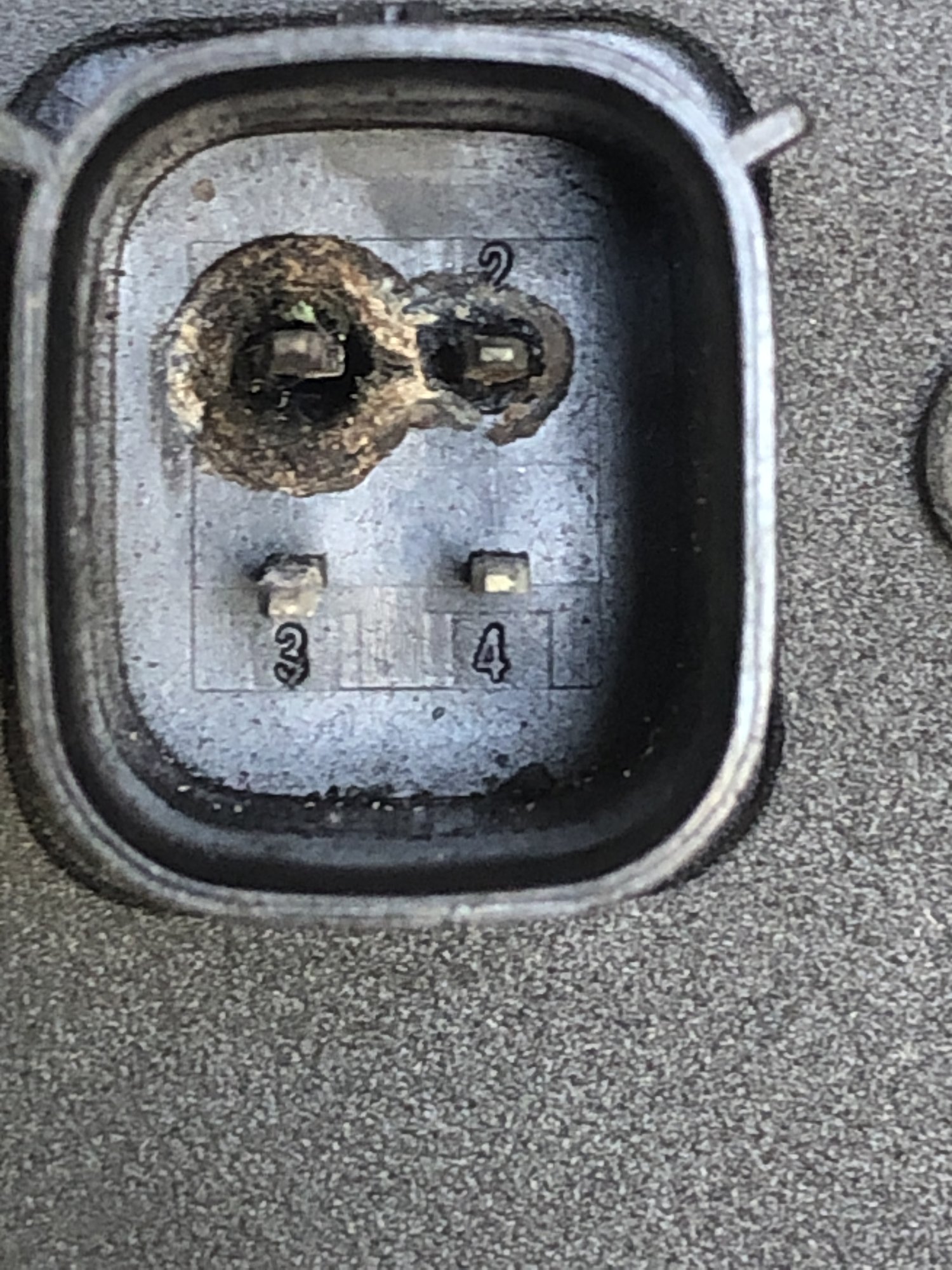
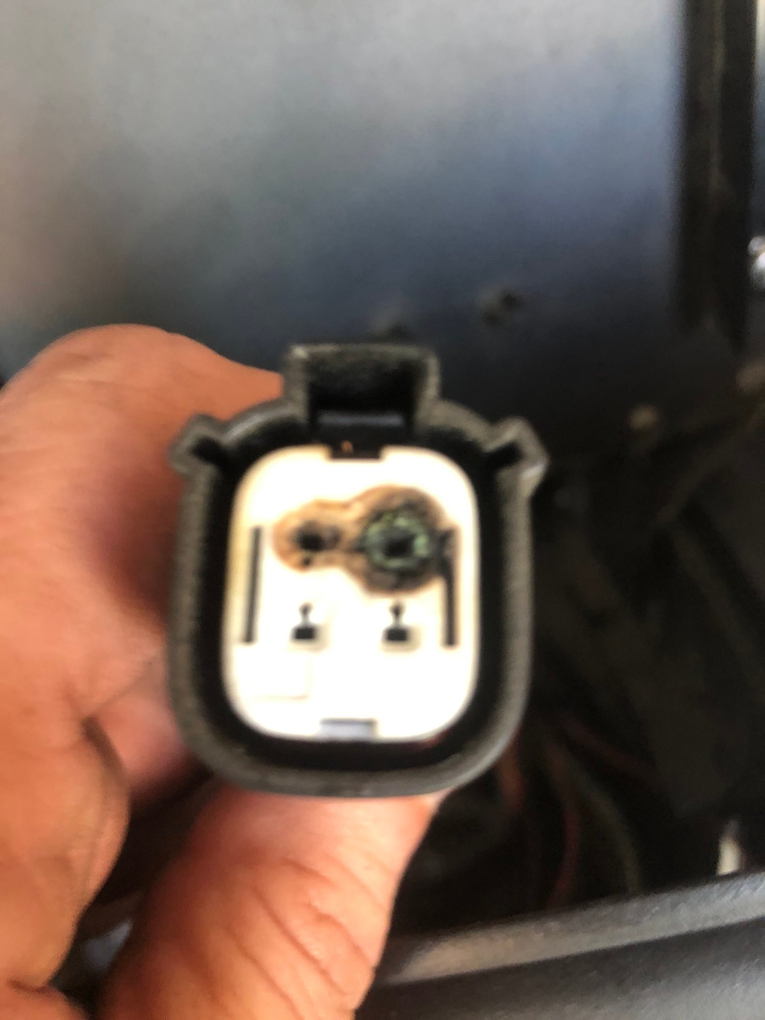
My connectors and plug were totally fried,
Fan didnt operate at all with this level of connector damage.
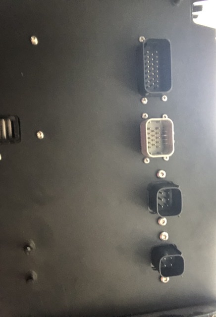
I pulled the pem and the 2 boards that are required to get to the CIC board which has the PEM Fan connector.
The right most connector is the PEM FAN one.
clean out the old solder holes carefully.... no drilling! just a solder vac and they blow out easily
after the work was done.
Its not that hard to do, just takes a little solder skills and a few hours to pull the PEM, replace the connector and put it all back together.
lots of screws and little parts to keep track of where they all go... but its doable.
Check out my post
PEM FAN Connector pin identification
which has a little more info and schematics for the two motor and fan lines.
Thanks, and yes, I've already studied your post. Excellent work.I actually just went thru this with my car. I dont know if I would BRIDGE those two together as if one is powered and the other isnt, it might cause an issue with the PEM.
I ended up for now replacing the connectors. As @PV-EV noted, you need to pull the whole pem to replace the connector as its screwed on with 2 torx screws on bottom.
My connectors and plug were totally fried,
Fan didnt operate at all with this level of connector damage.
I pulled the pem and the 2 boards that are required to get to the CIC board which has the PEM Fan connector.
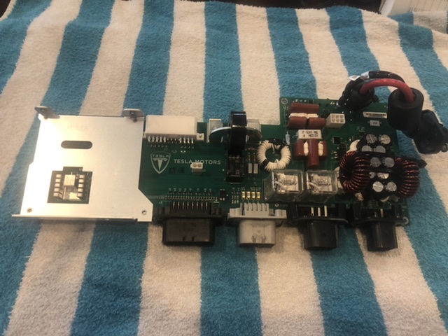
The right most connector is the PEM FAN one.
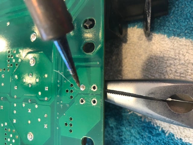
clean out the old solder holes carefully.... no drilling! just a solder vac and they blow out easily
after the work was done.
Its not that hard to do, just takes a little solder skills and a few hours to pull the PEM, replace the connector and put it all back together.
lots of screws and little parts to keep track of where they all go... but its doable.
Check out my post
PEM FAN Connector pin identification
which has a little more info and schematics for the two motor and fan lines.
The thing is, note that only your two positive pins are fried, not the two negative. Other pictures I've seen posted show similar, if not quite so dramatic. That's what has me puzzled. @MLAUTO said that it's likely both positive pins are tied (potentially via a FET switch?) to the APS+ line, so they're kind of already wired together, which should distribute the power to both pins, assuming both fans are being asked to spin. Apparently, your motor is running hotter than the PEM, so that side got the brunt of it and apparently failed first. On my car, and in my driving, the PEM tends to lead in getting warm, so I'm expecting it's the side that failed.
But why the apparent preference for frying the positive pins?
More puzzle. Is APS- not tied to vehicle ground? If the positive side is tied to APS+, I shouldn't be able to drive a 6w lamp between the under-car positive terminal and the vehicle chassis (the bolt holding the sway arm, for example). It appears that the entire fan driver circuitry is totally isolated from the car. Or at least that bolt. Really?
Oh, also I just realized that I probably shouldn't be taking my meter's 13.4v reading at face value. If I switch the meter to AC, I see it twitching, so (duh!) the supply to the blower motor is pulse-width modulated. While I still can't get it to light a 6w bulb, need to get an oscilloscope on it to see what exactly is going on. The 13.4v may simply be a tiny bit of leakage through the PEM's drivers, showing voltage and no current, which is in fact what I'm seeing. I tried leaving the lamp connected from cold to getting a 1144 alert while charging, and still did not see the lamp lighting after the alert. Need to wire up a small harness so I can get a set of scope probes on it with the lamp in place.
Any corrections to the diagram?
Similar threads
- Replies
- 32
- Views
- 3K
- Replies
- 16K
- Views
- 1M