I had asked the same question but the tech said it was just easier. They were able to install the neurio on the main panel instead of having to run the wires through the conduit from the PW+.Why would you use an additional Neurio when there are at least 3 empty CT channels in the Gateway 2 pictured in this thread? The only reason I can think of is that the distance exceeds normal CT wiring, which probably doesn't apply to this case. The reason the CTs are empty in this case is that the solar production is reported digitally by the Tesla inverter. Adding 3rd party solar would require CT metering to be logically added in the Gateway to the solar quantity reported by the Tesla inverter.


Welcome to Tesla Motors Club
Discuss Tesla's Model S, Model 3, Model X, Model Y, Cybertruck, Roadster and More.
Register
Install the app
How to install the app on iOS
You can install our site as a web app on your iOS device by utilizing the Add to Home Screen feature in Safari. Please see this thread for more details on this.
Note: This feature may not be available in some browsers.
-
Want to remove ads? Register an account and login to see fewer ads, and become a Supporting Member to remove almost all ads.
You are using an out of date browser. It may not display this or other websites correctly.
You should upgrade or use an alternative browser.
You should upgrade or use an alternative browser.
Want to add separate DIY system to existing Tesla solar and Powerwalls. Where to connect?
- Thread starter ascottallison
- Start date
miimura
Well-Known Member
Ok, I went back and re-read this thread and I see where I went off track.If you had a backup switch instead of GW2.
@wwhitney was pondering how to properly do PV Production Metering with a utility provided meter and a Powerwall+ and you (@Vines) answered regarding Tesla CT metering. Then @dailo interjected with Backup Switch +Neurio for Tesla solar measurement.
In the big picture, getting the solar measurement into the Tesla system so Powerwalls behave as expected has a couple solutions and is relatively easy. How to add solar when your utility requires production metering raises the complexity a bit.

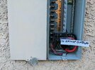
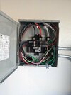
Thank you everyone for your help on this matter! I had a closer look at the inverter and have discovered there's a Neurio on the right hand side, with a single CT connected (1 of 4 ports). The Generac branded CT is hiding on the left hand side.

Here's the CT:

My strings are connected in the top right pattern shown here "4 combined strings":

According to this sketch Tesla gave me this is how the strings are wired:
Panels are Q-Cell 340W (each have a max of 40V) - so the string of 7 has a voltage of 7 * 40V = 280V
.jpg")
Blue string faces south and the red string faces east. The West roof has pool solar on it, except the NW corner which Tesla were originally going to put 4 panels on but then changed their mind and moved them to the south roof on the day of install.
Here's the CT:
My strings are connected in the top right pattern shown here "4 combined strings":
According to this sketch Tesla gave me this is how the strings are wired:
- String 1 has 2 strings of 5 panels in parallel
- String 2 has 2 strings of 7 panels in parallel
Panels are Q-Cell 340W (each have a max of 40V) - so the string of 7 has a voltage of 7 * 40V = 280V
Blue string faces south and the red string faces east. The West roof has pool solar on it, except the NW corner which Tesla were originally going to put 4 panels on but then changed their mind and moved them to the south roof on the day of install.
Last edited:
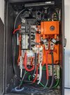
I believe the output from Tesla PVs goes directly to the GW. So any new PVs would need to be connected to GW directly.I have just received PTO on an 8.16 kWh Tesla solar system with 2 powerwalls (see photos). I have whole home back up. However, PV isn't quite enough for my needs, one reason being that Tesla wouldn't entertain installing panels on a porch roof (which can definitely hold them). So, my brilliant idea is to put up 4 panels on there myself with micro inverters. The panels I've picked out are 440W so it would take total PV array size to just a hair under 10 kW. I may have room elsewhere for 3 more, which would take it to 11.2 kW.
I like DIY and am confident with regular electrics. However, I'm not clear where to connect the output from the micro inverters to. It seems like the logical place to do so is the "PV combiner panel", but that's actually the output from the Powerwalls, not directly the PV. I've also read here that the powerwall needs to be aware of all solar if it's to charge from them. I've no idea where the CTs are, I've looked and the only obvious ones are built into the backup gateway.
So I'm looking for your help and advice! I'd hire an electrician but sceptical I can find someone who understands Tesla ESS. This isn't really any different from someone who had an existing PV only system them installed a separate Tesla solar system with Powerwalls. So I know this is possible I just don't know how to do it. Wishing now that I'd got the number of the Tesla electrician who installed it in the first place.
I have two service panels and a GW for each, but total three inverters power 2>1 and 1>1 configuration.
I myself am planning on adding more panels as the existing setup is only good during sunny days, and winter is only 3 months away.
Please let us know if you make a breakthrough as you’ve already purchased the miPVs
CrazyRabbit
Active Member
I like the option of adding additional panels to the Tesla inverter. How are your stings connected to the inverter? Are any of your stings combined to more then one mppt.
I didn't make a breakthrough. It's still something I want to figure out but the added complication of the separate solar meter was another layer. I suspect if I just connect at the small breaker box marked "PV combiner panel" it will all work just fine, but it wouldn't show the additional production in the app and possibly might screw up the other numbers? Something I may look at again this coming winter once it's cooler outside. Too hot in Vegas right now to be messing around with panels outside!I believe the output from Tesla PVs goes directly to the GW. So any new PVs would need to be connected to GW directly.
I have two service panels and a GW for each, but total three inverters power 2>1 and 1>1 configuration.
I myself am planning on adding more panels as the existing setup is only good during sunny days, and winter is only 3 months away.
Please let us know if you make a breakthrough as you’ve already purchased the miPVs
Yeah, me too. This would absolutely be my preferred option but sadly I have 4 sets of strings, combined in pairs, so there's no spare capacity in the inverter. Annoyingly one pair of strings could actually be in series and if it were, that would leave me with one MPPT spare. But of course changing the configuration from Tesla's designs would likely cause warranty issues if later discovered.I like the option of adding additional panels to the Tesla inverter. How are your stings connected to the inverter? Are any of your stings combined to more then one mppt.
syedali2021
Member
I found the PV and inverter system spec online, may help with figuring out proper setup. If you know the voltage/series going into the inverter can’t you just add another series of matching PV voltage in parallel?
https://tesla-cdn.thron.com/static/...er-solar-shutdown-device-datasheet-en-na.pdf"
https://tesla-cdn.thron.com/static/...er-solar-shutdown-device-datasheet-en-na.pdf"
Vines
Active Member
Theoretically if you want to add things nothing except your warranty is stopping you.I found the PV and inverter system spec online, may help with figuring out proper setup. If you know the voltage/series going into the inverter can’t you just add another series of matching PV voltage in parallel?
https://tesla-cdn.thron.com/static/IPSQHF_solar-inverter-solar-shutdown-device-datasheet-en-na_NI9SRF.pdf?xseo=&response-content-disposition=inline;filename="solar-inverter-solar-shutdown-device-datasheet-en-na.pdf"
Practically where will you get the extra MCI to install another string?
CrazyRabbit
Active Member
Your PV combiner panel is improperly labeled as back feed. Your breakers should have hold down kit and compatible breakers, and perhaps the should the connection in the gateway too. Perhaps the black bracket is suitable for this.
Don’t know the bus size in your combiner panel. But seems reasonable to land the output of a enphase combiner to it, capacity excluded. Don’t know if Tesla locks down the setting in everything…. 80 breaker in GW would need to be changed, and perhaps wire gauge.
Did Tesla add the 125 amp disconnect breaker to the distribution panel? Is there a breaker in the meter panel out side?
I get powerwalls and solar installed next week, and have enphase solar. I WILL pay attention to the CT locations.
As someone stated before, the system still works in off grid mode w/o neurio working, so probably just required for app power flows.
Sorry, I only just noticed your reply.Your PV combiner panel is improperly labeled as back feed. Your breakers should have hold down kit and compatible breakers, and perhaps the should the connection in the gateway too. Perhaps the black bracket is suitable for this.
Don’t know the bus size in your combiner panel. But seems reasonable to land the output of a enphase combiner to it, capacity excluded. Don’t know if Tesla locks down the setting in everything…. 80 breaker in GW would need to be changed, and perhaps wire gauge.
Did Tesla add the 125 amp disconnect breaker to the distribution panel? Is there a breaker in the meter panel out side?
I get powerwalls and solar installed next week, and have enphase solar. I WILL pay attention to the CT locations.
As someone stated before, the system still works in off grid mode w/o neurio working, so probably just required for app power flows.
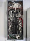
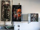
Yes, both the load panel inside and the original one outside have 125A breakers. Photos below.
Are you up and running now? Can you share details of how everything was connected?
Attachments
CrazyRabbit
Active Member
I would land additional solar directly to the internal panel board in the gateway, where you can use the internal CT ports to monitor the additional solar production.
The bus bars of the internal panel board are rated for 200 amps with 125amp maximum breakers.
So do enphase with envoy combiner box, and you can self commission enphase solar.
As far as safety devices I would follow the existing design. It looks like they didn’t install the big red button, so I don’t know how your system is to be disabled. So you might need a disconnect switch somewhere, perhaps outside.
My install thread Installation is starting - 8 PW and 12 solar panels
Last edited:
Thanks. I think your suggestion would work but the new solar would bypass the solar generation meter.
There is a big red button on the outside wall. I believe it connects in to the inverter on the PW+
There is a big red button on the outside wall. I believe it connects in to the inverter on the PW+
Similar threads
- Replies
- 5
- Views
- 384
- Replies
- 23
- Views
- 1K
- Replies
- 11
- Views
- 622
- Replies
- 0
- Views
- 207
- Replies
- 32
- Views
- 930