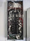
I have just received PTO on an 8.16 kWh Tesla solar system with 2 powerwalls (see photos). I have whole home back up. However, PV isn't quite enough for my needs, one reason being that Tesla wouldn't entertain installing panels on a porch roof (which can definitely hold them). So, my brilliant idea is to put up 4 panels on there myself with micro inverters. The panels I've picked out are 440W so it would take total PV array size to just a hair under 10 kW. I may have room elsewhere for 3 more, which would take it to 11.2 kW.
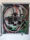
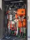
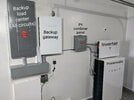
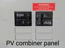
I like DIY and am confident with regular electrics. However, I'm not clear where to connect the output from the micro inverters to. It seems like the logical place to do so is the "PV combiner panel", but that's actually the output from the Powerwalls, not directly the PV. I've also read here that the powerwall needs to be aware of all solar if it's to charge from them. I've no idea where the CTs are, I've looked and the only obvious ones are built into the backup gateway.
So I'm looking for your help and advice! I'd hire an electrician but sceptical I can find someone who understands Tesla ESS. This isn't really any different from someone who had an existing PV only system them installed a separate Tesla solar system with Powerwalls. So I know this is possible I just don't know how to do it. Wishing now that I'd got the number of the Tesla electrician who installed it in the first place.
Attachments
Last edited: