BigMskiman
Active Member
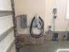
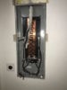
It's 3/4" EMT conduit, #8 THHN Cu wire, 50amp breaker serving 40amps to Mortimer.It looks like the 3/4" knockout placement on a typical 4x4 box, but the perspective/angle doesn't allow that to be guaranteed.
I'd ask if there's any reason for the 4x4 box there - leaving for NEMA 14-50? Otherwise I would have just used an LB pull box there to save some space.
My guy dislikes sharp right angle bends into HPWC, so he put that box. More importantly, the source is on the opposite garage wall (it goes up & over currently) and he put another box there too. So if we decide to park MX on the left someday, HPWC goes with it, ready to go.
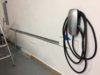
") . I felt I needed a little over 8', I don't know why the other option is 24', but 24' is A LOT of cable. You can come visit & charge, park out by the barn, looks like it'll reach just about the whole driveway. Updates on install will, of course, follow. ML
. I felt I needed a little over 8', I don't know why the other option is 24', but 24' is A LOT of cable. You can come visit & charge, park out by the barn, looks like it'll reach just about the whole driveway. Updates on install will, of course, follow. ML