


Welcome to Tesla Motors Club
Discuss Tesla's Model S, Model 3, Model X, Model Y, Cybertruck, Roadster and More.
Register
Install the app
How to install the app on iOS
You can install our site as a web app on your iOS device by utilizing the Add to Home Screen feature in Safari. Please see this thread for more details on this.
Note: This feature may not be available in some browsers.
-
Want to remove ads? Register an account and login to see fewer ads, and become a Supporting Member to remove almost all ads.
You are using an out of date browser. It may not display this or other websites correctly.
You should upgrade or use an alternative browser.
You should upgrade or use an alternative browser.
Wireless front parking camera with monitor for front bumper protection
- Thread starter artsci
- Start date
-
- Tags
- Model S User Interface
@WhiteP85, BTW I'd be willing to contribute $50 to your get a camera fund if you'd like.
This is the best news I've had all month.
Not to worry about costs now. When the PCBs and enclosures are ready WhiteP85 and I will collaborate a kit at close to cost, and that will include development costs, which I don't think are that high. The Tesla camera will be by far the most expensive item for this modification (about $350 I think). WhiteP85 and I have been volunteering our time all along.
For those of you who purchased the Chinese cables for this mod when they were first offered, please PM me now. I'm arranging a deal with the Chinese company for free replacement cables. Corrected cables are on the way to me from China now, WhiteP85 will be testing them to be sure they work ok. If they work, the corrected cable kit will be available again from the same Chinese source and I will arrange for free shipments of the corrected cables to those who bought the bad cables.
Berkut
Member
Good news! The new board works and switches the cameras so the hard part is done!
Congratulations on conquering those technical hurdles! - Job well done.
Gizmotoy
Active Member
I'm pretty excited about this. Even with the parking sensors I managed to slightly ding the lower black part of the front bumper the first week I had the car. Looks like a pretty elegant solution.
WhiteP85
Member
@WhiteP85, BTW I'd be willing to contribute $50 to your get a camera fund if you'd like.
Thanks for the kind offer but I actually have a second camera and will be able to test with it soon.
") Artsci has been using it for the design of the camera bracket.
Artsci has been using it for the design of the camera bracket.ken830
Model S 85, Model 3 Performance, Model X LongRange
Congrats WhiteP85!
Maybe soon, we can work on adding cameras under the side mirrors and then combine all four video streams to create an all-around birds-eye view video that we can switch to with a touch of the screen!
Maybe soon, we can work on adding cameras under the side mirrors and then combine all four video streams to create an all-around birds-eye view video that we can switch to with a touch of the screen!
WhiteP85
Member
Congrats WhiteP85!
Maybe soon, we can work on adding cameras under the side mirrors and then combine all four video streams to create an all-around birds-eye view video that we can switch to with a touch of the screen!
Thanks. We should add rotor blades to the car and add a camera to the bottom too ;-)
Gizmotoy
Active Member
Warning, trailer hitch detected in road! :wink:Thanks. We should add rotor blades to the car and add a camera to the bottom too ;-)
I'm pretty excited about this. Even with the parking sensors I managed to slightly ding the lower black part of the front bumper the first week I had the car. Looks like a pretty elegant solution.
Yes, with this I don't think parking sensors will be necessary. That was the idea to begin with. As my car is now off for repairs to the front end, which will include replacement of the front bumper, I thought maybe I should add the sensors. But I decided that with the front camera I won't need them. My hat is off to Whitep85 for solving what was a very difficult technical challenge.
Gizmotoy
Active Member
How much of the car will need to come apart for this? I tried to figure it out, but didn't have much luck with this thread up to 40+ pages now. Presumably the front cone, up into the frunk fusebox, through the firewall, and to the removal of the 17" display/computer unit in order to get at the camera input to plug into the switch?
How much of the car will need to come apart for this? I tried to figure it out, but didn't have much luck with this thread up to 40+ pages now. Presumably the front cone, up into the frunk fusebox, through the firewall, and to the removal of the 17" display/computer unit in order to get at the camera input to plug into the switch?
Not much. The only real challenge is threading the camera cable through the front grille and up into the space under the driver's side frunk cover panel. Not sure if the bumper has to be removed for that, but probably not if we know the route through the spaces that can't be seen. Holes in the firewall are definitely not necessary, and not recommended. The cable then threads through the narrow space in the driver's side fender and into the kick panel, where the PCB will be mounted and the touch screen connection made. As the short cable that connects to the touchscreen is easily accessible under that kick panel, there is no need to remove or otherwise mess with the touchscreen itself.
Think of it this way. The PCB will have three simple plug in connections, one each for the front and rear camera and the other for the touchscreen. This will be made with a set of the Chinese cables or the Tesla cables. Power will be provided from Tesla's current camera system itself so there should be no need for a connection to the fuse box.
It really should be quite easy.
Gizmotoy
Active Member
That sounds vastly easier than I pictured. Really excellent work. Major kudos.Not much. The only real challenge is threading the camera cable through the front grille and up into the space under the driver's side frunk cover panel. Not sure if the bumper has to be removed for that, but probably not if we know the route through the spaces that can't be seen. Holes in the firewall are definitely not necessary, and not recommended. The cable then threads through the narrow space in the driver's side fender and into the kick panel, where the PCB will be mounted and the touch screen connection made. As the short cable that connects to the touchscreen is easily accessible under that kick panel, there is no need to remove or otherwise mess with the touchscreen itself.
Think of it this way. The PCB will have three simple plug in connections, one each for the front and rear camera and the other for the touchscreen. This will be made with a set of the Chinese cables or the Tesla cables. Power will be provided from Tesla's current camera system itself so there should be no need for a connection to the fuse box.
It really should be quite easy.
Is there an alternative mounting place if you don't have a front plate? I might have a plate installed just to support this, otherwise.
That sounds vastly easier than I pictured. Really excellent work. Major kudos.
Is there an alternative mounting place if you don't have a front plate? I might have a plate installed just to support this, otherwise.
Yes, the camera can be mounted (glued or with double face tape) to the grille below the nose cone. That's what I've done. See photo. That camera above it is now gone.
WhiteP85
Member
After further testing with the front and back camera I have found that the 12 volt power inside the camera cable is not stable enough to use to power the switch circuit. Tesla toggles the power on and off when no camera is detected and this prevents the camera switch electronics from working and being able to switch. This left me with a couple of alternatives. I could build a new circuit with battery backup as part of the switch or could simply power the switch externally. I took the path of least resistance and decided to go with external power.
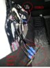
To keep the installation as simple as possible I wanted to avoid having to run power cables or tap into existing power leads. According to Pete8314 one can tap into the power in the wiring harness but this is not ideal for a DIY install but luckily there is also power in the OBDII connector very close to where the switch will be installed. To test I ordered a plug for the OBDII connector and wired it up to the switch as shown below.

The OBDII plug I used looks like this and plugs in easily to the existing socket. There is no cover on this particular plug so I might try and source an alternative that shields the wiring.

With stable 12V power the camera switch works as designed. Here is a link to a quick video. Tesla Model S Camera Switch with front and back camera - YouTube
The front camera was placed on the hood for testing.

The other good news is that one of the short Chinese LVDS jumper cables was used in the test so we at least know that they work for short runs.
So we are close now and my next step is to correct the PCB and prototype what I hope will be the production design.
To keep the installation as simple as possible I wanted to avoid having to run power cables or tap into existing power leads. According to Pete8314 one can tap into the power in the wiring harness but this is not ideal for a DIY install but luckily there is also power in the OBDII connector very close to where the switch will be installed. To test I ordered a plug for the OBDII connector and wired it up to the switch as shown below.
The OBDII plug I used looks like this and plugs in easily to the existing socket. There is no cover on this particular plug so I might try and source an alternative that shields the wiring.
With stable 12V power the camera switch works as designed. Here is a link to a quick video. Tesla Model S Camera Switch with front and back camera - YouTube
The front camera was placed on the hood for testing.
The other good news is that one of the short Chinese LVDS jumper cables was used in the test so we at least know that they work for short runs.
So we are close now and my next step is to correct the PCB and prototype what I hope will be the production design.
Attachments
Last edited:
gbdesai
Member
So we are close now and my next step is to correct the PCB and prototype what I hope will be the production design.
Sweet. Thanks for working through the holidays...
Thanks to WhiteP85 I think we can declare victory! Given that the corrected Chinese cable works I've just contacted RF Supplier in China about making corrected replacement kits for all of the orginal buyers. We have to test the long cable that connects the front camera to the PCB, and once that is done the kit of the corrected cables will go on sale for new buyers.
So stay tuned. If you were thinking of buying parking sensors you might want to consider this alternative, as it will be less expensive and easier to do. No holes in the bumper or sensor tabs on the bumper surface. And any obstacles in front of the car can be clearly seen, with it all controlled from the touch screen.
So stay tuned. If you were thinking of buying parking sensors you might want to consider this alternative, as it will be less expensive and easier to do. No holes in the bumper or sensor tabs on the bumper surface. And any obstacles in front of the car can be clearly seen, with it all controlled from the touch screen.
WhiteP85
Member
One of the desired features of this switch is the ability to automatically switch to the camera to rear when in reverse. The plan is to power a remote fob that uses one of the spare channels (there are 4 and one is used by homelink) by the reverse light power.
The question is - how can we get at the reverse light wiring? The obvious location is the tail light itself. Anyone know how remove the tail light to get at the wiring? Here is a photo showing the passenger side tail light. Looks like that black panel should come off first? I tried twisting the black knob and then tried prying up the knob without success. I was worried about breaking it so I did not apply much force.

The question is - how can we get at the reverse light wiring? The obvious location is the tail light itself. Anyone know how remove the tail light to get at the wiring? Here is a photo showing the passenger side tail light. Looks like that black panel should come off first? I tried twisting the black knob and then tried prying up the knob without success. I was worried about breaking it so I did not apply much force.
I'll get on this when my car comes back from the body shop. I need to figure this out anyway for lighting the rear T and triggering a higher level of brightness when the brakes are applied. But if anyone else already know the answer please post it.
WhiteP85
Member
Hi NielsChr. I read that this ODBII connector lacks actual CANbus but I have not tested or verified that myself. Reading the CANbus would be very elegant but also a new and more complicated solution. I have also never worked with CANbus so my preference is for a simpler solution to start with.
I have no current plans for recording as it is technically quite complicated to split, demultiplex, and convert this signal into a format that is readily recordable. I have had enough trouble just getting the switch to work ;-)
I have no current plans for recording as it is technically quite complicated to split, demultiplex, and convert this signal into a format that is readily recordable. I have had enough trouble just getting the switch to work ;-)
Similar threads
- Question
- Replies
- 3
- Views
- 705
- Replies
- 87
- Views
- 17K
- Replies
- 1
- Views
- 726
- Replies
- 5
- Views
- 2K