So I searched for and read all the other dashcam/radar detector install posts, and I took some of those ideas, and added my own. I figured I would share here what I did. I'm very happy with the results, which required ZERO hard wire tapping or splicing for power, and it did not use the 12V source in the microphone area, which my 15xxx car did not have (which I would have used, if it were there!). So I needed a different 12v source. I decided to use the OBDII port in the drivers' footwell area.
Here are the parts I used:
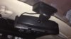
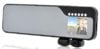
First, the dashcam -- $60 from China, plus $18 shipping. It clips onto the MS rear-view mirror very nicely. I miss the MS mirror, but I like the dashcam better.")

Link: Wholesale Car Dashcam - Rear view Mirror Camera From China
I liked this one because it had adjustable front and rear cameras. But as it turns out, the rear camera doesn't work so well with the MS since the darkness of the rear hatch changes the average exposure, so the back window itself is totally washed out during the day. The rear camera might work better at night, but I didn't try that yet.
So instead, I use two cameras facing forward for a much wider angle field of view to the left and right -- much more than one camera can deliver.
Other parts:
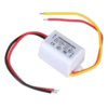
KEEDOX® DC/DC Converter 12V Step Down to 5V 3A Power Supply Module $4 at Amazon

30A 12/24VDC Mini Blade In-Line Fuse Holder : Fuse Holders | RadioShack.com $3.50

1/4 Fully Insulated Quick Disconnects (10-Pack) : Disconnects | RadioShack.com $2.99

1/4 Fully Insulated Quick Disconnects (10-Pack) : Disconnects | RadioShack.com $2.99

Low Profile Right/Left Angle OBD 2 II Extension with Flat Ribbon Cable 3/1m $10 at Amazon

Since the dashcam runs on USB power, I needed to step down 12V to 5.5V, which is what the KEEDOX unit does. It's pretty small. And if your car does have the 12V power in the microphone area, this converter WILL FIT in that area -- it's tight, but it will fit, so if you want to hook it up there, by all means, do that.
But if you don't have that 12V source, I decided to go with the OBDII port, which is always on. That's OK, since I can turn the dash cam on and off if I choose to do so. Otherwise, it draws very little current. Not enough that I'm worried about phantom draw.
So Step #1, was to cut off the 12V->USB power cable that came with the webcam -- it has a nice 10foot cable with the proper right-angle USB plug on the end. Discard the 12V end of the power adapter (cigarette plug). (or keep it for some other future project). I know it also has a 12v->5.5v converter, but I didn't want to bother with whatever was inside and creating an insulated housing for it. The KEEDOX was a nice, compact, self-contained unit to do the same thing for only 4 bucks.

Step #2: I soldered the + and - of the USB cable to the "output" end of the KEEDOX converter (off the left side of this photo). The red wire is positive and the yellow is negative (kind of obvious).
Step #3: On the "Input" side of the converter, I attached two of the Radio Shack insulated quick connects (the red ones are for smaller gauge wires):

Step #4: On the + side of the converter, I added a mini-blade 30amp fuse holder (and a 3A fuse), again using the radio shack quick connects (the blue ones are for larger guage wires). It's a huge fuse holder, but that's all Radio Shack had available on Saturday.

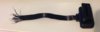
Step #5: (I did this in the car) Take the OBD extension cable, and cut off the FEMALE end, leaving most (but not all) of the wire attached to the MALE end (the end with the visible pins). Now fray out and strip the ends of the wire attached to the FEMALE end. On OBDII, pin 4 is chassis ground, and Pin 16 is +12V. But since I didn't have a pin out of the flat ribbon cable, I had to use trial and error. I used the FEMALE end to test each pin to find which wires were connected to Pins 4 and 16. Turns out that lead #5 was ground, and lead #8 was +12v. Don't ask me from which side to start counting, I just kept it straight (I actually cut the wire at a bias, so I had a long side, and short side to tell them apart). So I matched those leads to the MALE end, and re-tested the pins match up to the pinout. I then plugged in the MALE end into the OBDII port on the car to confirm I had the correct + and - leads. They were correct, so I pulled the OBDII plug and took it to my work bench to solder the rest of it up. Here's the FEMALE end I used for testing the pin out:

Step #6. The OBDII ribbon cable wires are VERY, VERY thin, so I first soldered some larger guage wire to each one, and shrink wrapped each wire connection, and then more shrink wrap around both joints. I also used some electrical tape to strengthen that end of the ribbon cable. (sorry, it's kind of hard to see this in the photos):

Step #7: To each end of the larger guage wire, I connected two more of the red Radio Shack quick connects. Which I then connected to the negative side of the KEEDOX converter, and the positive side to the other end of the fuse holder. Here's the finished product on the bench:

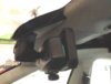
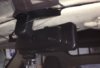
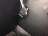
Step #8: Take the assembled cable to the car. Disconnect the ODBII cable from the rest of the bits using the quick connects. Remove the driver's side plastic side panel next to the dash when the door is open (same panel with the ethernet jack). You'll have to play with it, but you can feed the end of the OBDII wire up and through to this open area. Plug in the ODBII plug and pull through the rest of the slack in the OBBII wire. Bad photo, but this is what it looks like from below:

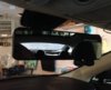
Step #9: Mount the dashcam on the rear-view mirror (it just slides on), plug in the USB cable to the cam, and make sure there's enough slack to move the mirror around without pulling the cable. Using a plastic pry tool, lift the front top edge of the windshield trim away from the windshield, and insert the wire. Move along the top moving to the left. It's pretty easy. Then route the wire around (and inside) the A pillar, and into the side molding moving down, under the black rubber weather stripping. Again, this is pretty straight forward if you have a good pry tool. Then feed the wire down into the open panel area.
Step #10: Hook everything up! Connect the ends of the OBDII cable to the fuse holder and converter. Plug in the dashcam. If you did everything right, it should power up. You can wrap up the excess cable and place it inside that open area behind the dash. Replace the trim panel, and you're done!
Notes: Since I used the quick-connects, when it comes time to install the Front-Rear Touchscreen Camera Kit, I can use a couple more quick connects to tap into this power source which is already fused and powered by the OBDII port. And if I'm parking the car and not using it for any long period of time, I can just pull the OBDII plug to power down the dashcam and Front Camera module.
If I had to do it all over, I'd probably order a better OBDII cable what isn't a ribbon cable -- something like this:
Amazon.com: Oem OBD-II OBD2 16Pin Male to Female Extension Cable Diagnostic Extender 100cm: Electronics
When it comes time to install the Front-Rear cam, I may re-do the OBD cable part.
To remove everything, just disconnect the quick-connects, and pull the dashcam USB wire out of the moldings and trim, and unplug the OBDII cable and pull it out. There are no traces whatsoever of the install.
I'll post a sample video from the dashcam shortly.
Good luck!
Here are the parts I used:
First, the dashcam -- $60 from China, plus $18 shipping. It clips onto the MS rear-view mirror very nicely. I miss the MS mirror, but I like the dashcam better.
Link: Wholesale Car Dashcam - Rear view Mirror Camera From China
I liked this one because it had adjustable front and rear cameras. But as it turns out, the rear camera doesn't work so well with the MS since the darkness of the rear hatch changes the average exposure, so the back window itself is totally washed out during the day. The rear camera might work better at night, but I didn't try that yet.
So instead, I use two cameras facing forward for a much wider angle field of view to the left and right -- much more than one camera can deliver.
Other parts:
KEEDOX® DC/DC Converter 12V Step Down to 5V 3A Power Supply Module $4 at Amazon
30A 12/24VDC Mini Blade In-Line Fuse Holder : Fuse Holders | RadioShack.com $3.50
1/4 Fully Insulated Quick Disconnects (10-Pack) : Disconnects | RadioShack.com $2.99
1/4 Fully Insulated Quick Disconnects (10-Pack) : Disconnects | RadioShack.com $2.99
Low Profile Right/Left Angle OBD 2 II Extension with Flat Ribbon Cable 3/1m $10 at Amazon
Since the dashcam runs on USB power, I needed to step down 12V to 5.5V, which is what the KEEDOX unit does. It's pretty small. And if your car does have the 12V power in the microphone area, this converter WILL FIT in that area -- it's tight, but it will fit, so if you want to hook it up there, by all means, do that.
But if you don't have that 12V source, I decided to go with the OBDII port, which is always on. That's OK, since I can turn the dash cam on and off if I choose to do so. Otherwise, it draws very little current. Not enough that I'm worried about phantom draw.
So Step #1, was to cut off the 12V->USB power cable that came with the webcam -- it has a nice 10foot cable with the proper right-angle USB plug on the end. Discard the 12V end of the power adapter (cigarette plug). (or keep it for some other future project). I know it also has a 12v->5.5v converter, but I didn't want to bother with whatever was inside and creating an insulated housing for it. The KEEDOX was a nice, compact, self-contained unit to do the same thing for only 4 bucks.
Step #2: I soldered the + and - of the USB cable to the "output" end of the KEEDOX converter (off the left side of this photo). The red wire is positive and the yellow is negative (kind of obvious).
Step #3: On the "Input" side of the converter, I attached two of the Radio Shack insulated quick connects (the red ones are for smaller gauge wires):
Step #4: On the + side of the converter, I added a mini-blade 30amp fuse holder (and a 3A fuse), again using the radio shack quick connects (the blue ones are for larger guage wires). It's a huge fuse holder, but that's all Radio Shack had available on Saturday.
Step #5: (I did this in the car) Take the OBD extension cable, and cut off the FEMALE end, leaving most (but not all) of the wire attached to the MALE end (the end with the visible pins). Now fray out and strip the ends of the wire attached to the FEMALE end. On OBDII, pin 4 is chassis ground, and Pin 16 is +12V. But since I didn't have a pin out of the flat ribbon cable, I had to use trial and error. I used the FEMALE end to test each pin to find which wires were connected to Pins 4 and 16. Turns out that lead #5 was ground, and lead #8 was +12v. Don't ask me from which side to start counting, I just kept it straight (I actually cut the wire at a bias, so I had a long side, and short side to tell them apart). So I matched those leads to the MALE end, and re-tested the pins match up to the pinout. I then plugged in the MALE end into the OBDII port on the car to confirm I had the correct + and - leads. They were correct, so I pulled the OBDII plug and took it to my work bench to solder the rest of it up. Here's the FEMALE end I used for testing the pin out:
Step #6. The OBDII ribbon cable wires are VERY, VERY thin, so I first soldered some larger guage wire to each one, and shrink wrapped each wire connection, and then more shrink wrap around both joints. I also used some electrical tape to strengthen that end of the ribbon cable. (sorry, it's kind of hard to see this in the photos):
Step #7: To each end of the larger guage wire, I connected two more of the red Radio Shack quick connects. Which I then connected to the negative side of the KEEDOX converter, and the positive side to the other end of the fuse holder. Here's the finished product on the bench:
Step #8: Take the assembled cable to the car. Disconnect the ODBII cable from the rest of the bits using the quick connects. Remove the driver's side plastic side panel next to the dash when the door is open (same panel with the ethernet jack). You'll have to play with it, but you can feed the end of the OBDII wire up and through to this open area. Plug in the ODBII plug and pull through the rest of the slack in the OBBII wire. Bad photo, but this is what it looks like from below:
Step #9: Mount the dashcam on the rear-view mirror (it just slides on), plug in the USB cable to the cam, and make sure there's enough slack to move the mirror around without pulling the cable. Using a plastic pry tool, lift the front top edge of the windshield trim away from the windshield, and insert the wire. Move along the top moving to the left. It's pretty easy. Then route the wire around (and inside) the A pillar, and into the side molding moving down, under the black rubber weather stripping. Again, this is pretty straight forward if you have a good pry tool. Then feed the wire down into the open panel area.
Step #10: Hook everything up! Connect the ends of the OBDII cable to the fuse holder and converter. Plug in the dashcam. If you did everything right, it should power up. You can wrap up the excess cable and place it inside that open area behind the dash. Replace the trim panel, and you're done!
Notes: Since I used the quick-connects, when it comes time to install the Front-Rear Touchscreen Camera Kit, I can use a couple more quick connects to tap into this power source which is already fused and powered by the OBDII port. And if I'm parking the car and not using it for any long period of time, I can just pull the OBDII plug to power down the dashcam and Front Camera module.
If I had to do it all over, I'd probably order a better OBDII cable what isn't a ribbon cable -- something like this:
Amazon.com: Oem OBD-II OBD2 16Pin Male to Female Extension Cable Diagnostic Extender 100cm: Electronics
When it comes time to install the Front-Rear cam, I may re-do the OBD cable part.
To remove everything, just disconnect the quick-connects, and pull the dashcam USB wire out of the moldings and trim, and unplug the OBDII cable and pull it out. There are no traces whatsoever of the install.
I'll post a sample video from the dashcam shortly.
Good luck!
Attachments
-
 cord.jpg18.7 KB · Views: 7,234
 -
 OBD.JPG100.5 KB · Views: 7,199
 -
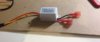 photo 1.JPG101.9 KB · Views: 7,221
 -
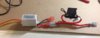 photo 2.JPG99.6 KB · Views: 7,277
 -
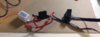 photo 3.jpg81.6 KB · Views: 7,151
 -
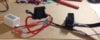 photo 4.JPG86.8 KB · Views: 7,196
 -
 dashcam.jpg43.6 KB · Views: 5,875
 -
 keedox.jpg20.4 KB · Views: 5,844
 -
 female obd.jpg52.7 KB · Views: 7,497
Last edited: