Welcome to Tesla Motors Club
Discuss Tesla's Model S, Model 3, Model X, Model Y, Cybertruck, Roadster and More.
Register

BMS Balancing - Current Understanding

This site may earn commission on affiliate links.
This is an interesting deep dive, but I guess the important question, has the car flagged any of this as abnormal by triggering a fault?
Nope no errors!

I know I have written a lot and shared deep, but my case does not seem to be covered by Jason Hughes info, nor the FB/Tesla BMS_u018/BMS_u029/BMS_a066 professionals :-(

I have not postponed software updates, so the special case, that when users refused the many software updates with improvements to fix Range after the 2019.10.* Voltage CAP, they were opting out of all the Diagnostics collection, performed during the update blocked period. Otherwise the car could perfectly well be in Diagnosis Mode still, because of my very small DepthOfDischarge around 40% SoC charge pattern, that may not reveal enough info to the BMS/Software :-(

Since 2020.48.37.2 (installed 12/06/2021 and the first update AFTER I adopted TeslaMate) I have performed 464 charges, but almost all were my daily cummute charges of <30%. But I have traveled 26.000 km ~ 16.000 miles.

1717513596810.png


Perhaps the BMS does not want to blead Bricks, because it is in 'Parasitic Drain Detection Mode' in which case bleading off Ah's may confuse that diagnosis?

Here is a manual drawn 'Floor' for all Average_Power used during Rests longer than 18 hours - it certainly does not rule out that I may have increasing number of very small parasitic drain(s) :-(

1717515373979.png
 

Attachments

  • 1717515157174.png
    1717515157174.png
    66.4 KB · Views: 4
Last edited:
@jensk2 Lots of theories. Unfortunately we are battling invisible stupid software logic without documentation. I have been battling nearly exact same problem. Nothing tried so far would improve my 20+ to 40+ mV imbalance (depending on SOC) My graphs are here ( link ) No fancy recalculations like your graphs. Just plain all 96 brick voltage readings swept across complete SOC window.

Lowest Imbalance also my GEOMEAN

My lowest imbalance is around 22mV at 70 SOC. This is also my GEOMEAN as I set to 70% SOC charge limit for years and made only 15+ mile trips between charging back to SOC.

@wk057 did post a reply the lowest imbalance is usually center of the SOC window due to smallest voltage deltas at these SOCs ( link )

Lowest Modules are 10 and 12

My lowest voltage modules are 10 and 12 AND all 6 bricks in each module are in balance with each other.

3Ah CAC

SMT (Android beta) reports 3Ah CAC

Screenshot_20240517-133703.png

Car Lose 4mi/day

On latest software in Advanced Mode (2022.8.10.17)
MCU1 Display->Energy Saving On

Disconnected pack doesn't lose capacity or increase imbalance

Car has sat with HV disabled for 2-3 months 2-3 times in the past 2 years for LDU coolant leak rebuild. HV battery didn't seem to lose capacity or any increase in imbalance during these long idle periods.

Attempted Balancing Efforts

Have tried 100% of 1/2 day, 95% for 2 days. Slowly charge 80-100% SOC at 5Amps etc.. No change to the imbalance.

Did see 4mV improvement @ 70 SOC ONCE after this long effort ( link sweep across 10% SOC intervals followed by > 6hr rest which I presume provides BMS with good calibration ) then charged it up to 95%

However, 4mV imbalance improvement was quickly lost (back to 22mV at 70 SOC) and haven't been able to see rebalancing effects again.

Parasitic Drain Mode Theory

Don't understand your "manual' draw floor graph from post #41. What is Y axis? since has no labels.

=====

Evidence seems to suggest is BMS is not triggering bleeding of the higher modules for some reason. It would be valuable if SMT can somehow extract BMS balancing state (each module/BMB's target voltage request) Will follow up with SMT developer if this is possible. This would give us at least and easy definitive info rather than wait and measure. Isn't easy to get precise SOC levels unless one had plenty of free time to watch SMT closely.

Maybe BMB problems?

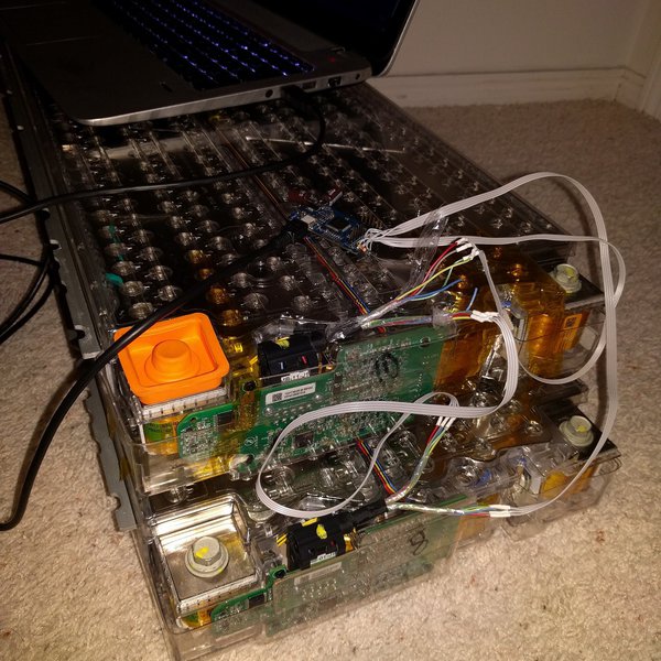
Having also worked with @mr_hyde on repairing his battery pack, I do wonder about moisture corrosion effect on the frontal module BMBs ( link ) My weak modules are 10 and 12 which are right side front 3 rows behind the hump. The upward facing AGM valve on top of the hump (Tesla remove on later pack revisions) just below windshield water dump through the wiper arm holes is likely culprit for frontal moisture along with plenty water spray from big wheel well holes. This is besides upward facing fuse cover and AC drain dump (even revised AC drain dump in front of hump rusted seams on @mr_hyde HV pack)

@jensk2 pack low modules are 2 5 11 13. 2 and 13 BMBs are next to each other and 5 and 11 are diagonal from each other but close by. Can't remember if 14 module cars skip module 8 and 9 numbering or use them to count up to 14 ( link )

Note ALL BMBs other than the 2 modules in the hump are located at center spline of the pack.

Unfortunately no easy visibility unless time consuming effort of pulled HV pack and non destructively peel off the lid ( WARNING Deadly dangerous and require ALL HV safety )
 
Update after discord chat with SMT dev. It seems most of what SMT gets are packets that shows up on CANBUS. CAN bus is how battery info gets to the MCU (presumably this is where some battery info can be displayed on MCU in for example diag mode) and then possibility get to the cloud.

SMT dev is unaware of any CANBUS packets as it related to balancing. He is not aware of balancing communication between BMS and BMBs such as BMS commanding BMBs to bleed to a target voltage showing up on the CANBUS. Nor are any BMS internal software state on rebalancing status.

So its easy to fly blind and if Tesla change the logic, even more so. I think people can observe rebalancing effect hours after it has occurred. But without any precision and exact knowledge on when it occurs. Nearly impossible to compare 2 exact same SOCs and car in the same state (quiet vs something active) Past discloser from @wk057 of bleed trigger at 93% was from his early pack teardown. Likely with lid open and an IR sensor pointing at the BMB bleed resistors (he showed a pic in the post). Probably no one has details if Tesla changed the logic since and in what way.

Anyway, probably need to converse with devs that has further developed the BMB communication software originally released by Colin at EVTV further to know if anything can be exposed externally. Their original project here

 
Last edited:
Jason Snip:
'Cell 6 of one module is physically connected to cell 0 of the next module, so with some clever use of balancing circuits within the pack, it’s possible to get yet another alternative voltage calculation for the erratic cell 6.'

It is pretty clear (with higher Y-axis resolution, that all Brick # MOD 6 == 0 bricks are 'undercharged'

If there really is multiple ways to measure cell 6, are we sure that SMT is showing the same measurement that BMS is using?

Maybe BMS notices the same thing , "ah crap, these cell6 measurements are too low, I'll just use another method" but the new measurements are not shown in SMT?

If you manually shift all cell6's to a bit higher, how does the balance look?
 
... CAN bus is how battery info gets to the MCU (presumably this is where some battery info can be displayed on MCU in for example diag mode) and then possibility get to the cloud.
since i have diag/dev modes, n u can have it display on IC, i was watching the brick voltages n noticed that its a lot more responsive than SMT
not sure if its just app lag or the way it averages but imbalance on IC pretty much always stays at 10mv for me as soon as i coast or stopped

1717684307912.png
 
since i have diag/dev modes, n u can have it display on IC, i was watching the brick voltages n noticed that its a lot more responsive than SMT
not sure if its just app lag or the way it averages but imbalance on IC pretty much always stays at 10mv for me as soon as i coast or stopped

View attachment 1054111

Thanks for noting IC's more accurate imbalance result. My guess is SMT on MS/X packs maybe limited by latency of BT transfer of all 96 bricks and imbalance calculation by the app. SMT dev said later (>=M3?) is faster, maybe BMS/MCU calculates it.

Perhaps the high level question is what pack failure signs can diag/SMT see?
  • 2 adjacent bricks with bad voltages seems to point to sensor wire connector / BMB corrosion.
  • Not sure a weak cell (one that isn't holding as much charge) would show
  • Not sure a broken cell fuse would show
  • Don't really know why mine and @jensk2 pack shows all 6 bricks balanced within a module but modules imbalanced against each other in 20-50mV range (car parked quietly and mostly with contactors open). I guess may need to tear open pack to gain more visibility... Hard to justify without car failing (slow and fast charge fine, nearly full original range etc)
 
I tend to conclude, that with a CAC ImBalance of 2% it makes sense to maintain a certain Voltage ImBalance (say up to 2% and 2% of 3.6V is 72 mV).

Any comments on whether this is likely or wishfull thinking?
this is a good theory n makes sense to me but who knows... no hard proof...

fyi, as i posted above, my car is always under 10mV imbalance n i barely ever go above 80% n below 20%

so my conclusion is Drive more worry less :)
 
  • Like
Reactions: jensk2
Parasitic Drain Mode Theory

Don't understand your "manual' draw floor graph from post #41. What is Y axis? since has no labels.
Thanks for a very thorough post!. As to your Q:, the TeslaMate graph shows the average power consumed/drain'ed during each rest period longer than 18 hours. Looking at TeslaMate Grafana Query for Vampire Drain, it seems to use drop in Range to calculate kWh's lost over the rest period, then divide by hours to reach Watts Average. My Manual drawn graph is going through all the Minimum Power Drawn points.

I read through your theory about Moist And BMB issues AND read that your Battery i V 1.5 (With FuseBox on top). My Battery is from 2015.10 and V2.0 with fusebox on bottom. But it is VERY CLEAR, that your battery does exactly what my battery does (or rather does not do).

I followed your links and noticed Jasons'comment:

'Overall, I usually suggest just letting the BMS do its job and not dwell on any particular metric.'

I do think that my Calulated CAC and Voltages document that the battery is not 'Best Case' balanced as a High CAC Brick (#12) will stop a drive first. I simply think the BMS just balances within experienced SoC Range and does not project to the Super Low SoC and Super High SoC as do I.

That was why I decided to try a much larger DoD to 'present' the data to the BMS, but as you, I have only seen a once improvement of up to 6 mV imbalance, newer to happen again. And I can semi confirm that my 'single' improvement is now vanishing (Large DoD Imbalance was down approx 6 mV and at 18 mV at 37% SoC, but is now up at 24 mV at 42% SoC :-(. Probably confirms, that the BMS balances within experinced SoC Range, now that I have mostly charged 20% - 70% as almost back to my old usage pattern, namely small DoD around 40% SoC.

(But how come some Batteries are always in almost 0 mV ImBalance, despite having a clear CAC ImBalance?? Does the BMS operate in several different moodes?? That brings back my previously mentioned option, that my BMS is constantly bleading almost all bricks to 'correct' for a stuck CMOS. If it only Blead off to compensate for parasitic loss, then ImBalance would either Improve or Degrade over time and not stay put as I kind of see)

I will stop stressing the battery cells and only do a few 90% Charges when it is of great convenience to charge that high. Then await what happens over a few months
 
Last edited:
If you manually shift all cell6's to a bit higher, how does the balance look?
All my bricks within each module are almost in (module) balance (within 3-4 mV). All Brick# MOD 6 == 0 are 1-3 mV below Brick# MOD 5 bricks.

If the Brick Voltage is reported by 10 bits and the #6 Bricks are missing a few LSB bits, it all could be CAN Bus issues. But why not balance on the Module Level then?

1717947918956.png
 
hard to see how a weak cell, open (blown fuse) cell, or shorted cell would cause 6 bricks to equalize within a module but not against other modules. Seems more likely its some problems with the BMB that handles the 6 bricks.

Maybe BMS is programmed to know this and avoid balancing? Seems unlikely Tesla would take such risks.
 
BMS also knows total voltage of each module, which should be the sum of all six cell voltages, but it is actually measured separately. This measurement is not shown in SMT.

Maybe there is a disagreement between this total volts and the sum of the six cell voltages? It might be that total voltages match even if individual cell voltages do not. There is always some inaccuracies in the ADC conversion..

Interesting, BMB has separate voltage sense circuit for module and the 6 bricks? I guess adding up 96 bricks to see if agree with total voltage probably won't work with potentially 96 x 0.5mV error.

I've also heard about ADC drift from other long time battery experts. I guess easy to determine if have access to inside the battery.