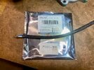
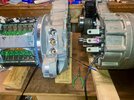
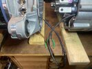
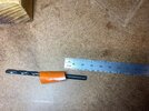
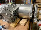
i used two jacks and pucks today to lift the car. pulled the speed sensor. i see a thick layer of brown grease on the top of it. put my finger in the hole and found more grease, but dont see coolant. might need a cheap borescope to see in the reluctor wheel area. attached pics.One floor jack is sufficient to get both tires up sitting on ~6" of wood to safely crawl under to remove the mid aero shield to check speed sensor. Just need to alternate between driver/passenger side a couple of times while building up height.
Regarding failure at 32k on reman RevQ, I'm guessing mine has been leaking for awhile judging by the rust on the rotor but no way to know for sure. Could have been much sooner. Just don't know.
If you do want to use the cedar cross beam to put the rear end on jack stands, may want to borrow 3rd floor jack to minimize bowing in center beam when lifting both ends of the beam.
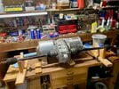
9" square platform should work if you find center of gravity (CG) on the drop. I was surprised by how stable the motor cycle jack was once CGed. Good trick is to safely land the subframe+LDU on something (jackstands in my case, had 6 total, 2x for rear lift pad, 4x for safety dropping subframe) after the 4 subframe bolts are removed and dropped a few inches. If not CGed (most likely won't be), subframe will tilt towards driver side as motor windings and rotor is where most of the weight is. The round inverter chamber looks same size as rotor but much lighter with electronics. So safely land it on something while reposition the tranny jack for CG.
If the tranny jack has an angled lifting arm (instead of scissor) then need to do the repeated 1/2" drop slide tranny jack/subframe assembly forward/backward 1/2" (backwards in my case) for few inches until the subframe clears the mid aero shield screw/bolt tabs. Have a 2nd person to help spot.
QC Charge tech @ajbessinger says they see many lower mileage LDUs with leak. So I'm guessing the the failure mode could be parking duration + reverse rather than many miles of forward rotation. @ajbessinger guess it could be sticking from parking. Not sure how one can confirm. Seal testing facilities probably can best answer. My shaft have some kind of stain along entire circumference seemingly at where the PTFE lips makes contact. Maybe is worn PTFE material embedding into the shaft surface? Anyway, there is a single spot along the circumference of the shaft where some kind of tapered hazy stain beyond the seal lips on the wet side. Hard to capture on camera with all the reflections but visually noticeable. Thinking about what this might be... doesn't seem like the rotor will sit at same rotation orientation on every park
View attachment 858534View attachment 858535
In my case, if it wasn't for the faint high pitch new noise, I probably wouldn't have googled and found the speed sensor removal test. Who knows, maybe could have gotten another 5 or 50k miles before louder bearing noise or catastrophic inverter or winding isolation failure. An interesting question on higher mileage DUs without catastrophic failures is if they have leaks. Wouldn't know unless one checked speed sensor. Maybe even speed sensor won't show if just the minutest of leak
====
Now onto finding and sourcing genuine bearings (a lot harder than I thought it would be). May have damaged an expensive ceramic bearing having to hammer out the rotor(think there is a way to get stuck rotor out safely. update at bottom of this post) Will post more updates soon.
Welcome to Tesla Motors Club
Discuss Tesla's Model S, Model 3, Model X, Model Y, Cybertruck, Roadster and More.
Register
Install the app
How to install the app on iOS
You can install our site as a web app on your iOS device by utilizing the Add to Home Screen feature in Safari. Please see this thread for more details on this.
Note: This feature may not be available in some browsers.
-
Want to remove ads? Register an account and login to see fewer ads, and become a Supporting Member to remove almost all ads.
You are using an out of date browser. It may not display this or other websites correctly.
You should upgrade or use an alternative browser.
You should upgrade or use an alternative browser.
Brown grease but no coolant. It is excess grease from the bearing, because what elso could it be. In that case it seems that you do not yet have a coolant leak. But is the bearing still sufficiently lubricated? Maybe it is, and "they" just put a bit too much grease in it. Who knows. By the way: Is there a ~5mm diameter drilled hole directly behind the original mounting location of the speed sensor?i used two jacks and pucks today to lift the car. pulled the speed sensor. i see a thick layer of brown grease on the top of it. put my finger in the hole and found more grease, but dont see coolant. might need a cheap borescope to see in the reluctor wheel area. attached pics.
i carefully wiped the sensor down. i found one drop that turned a napkin a tint of blue on the bottom side of the sensor, but not enough to concern me. the unit is a august 2017 original reman. i tried to get a pic inside the reluctor but will get a cheap borescope next time, cant tell if there is a 5mm hole yet. attaching du pn.Brown grease but no coolant. It is excess grease from the bearing, because what elso could it be. In that case it seems that you do not yet have a coolant leak. But is the bearing still sufficiently lubricated? Maybe it is, and "they" just put a bit too much grease in it. Who knows. By the way: Is there a ~5mm diameter drilled hole directly behind the original mounting location of the speed sensor?
Attachments
i carefully wiped the sensor down. i found one drop that turned a napkin a tint of blue on the bottom side of the sensor, but not enough to concern me. the unit is a august 2017 original reman. i tried to get a pic inside the reluctor but will get a cheap borescope next time, cant tell if there is a 5mm hole yet. attaching du pn.
Glad to see you may not have a leak
Like to get some clarification
Post #39 mentioned Rev Q and this sticker is Rev I. I'm assuming Rev I is correct?
Same post also mentioned 2020 LDU replacement @47k miles. LDU replaced at 30k miles. This post says 2017 LDU replacement. And current mileage is 65k. Can you clarify which is correct? Just gathering data for the LDU website to help understand characteristics of various LDU revisions.
Thanks
hi HowardGlad to see you may not have a leakPerhaps just check it every few months going forward. And if borescope can get a good view of seal's dry side, would be an awesome diag method and potential help to evaluate seal condition. I'd imagine need to be careful to not poke at the sealing lips.
Like to get some clarification
Post #39 mentioned Rev Q and this sticker is Rev I. I'm assuming Rev I is correct?
Same post also mentioned 2020 LDU replacement @47k miles. LDU replaced at 30k miles. This post says 2017 LDU replacement. And current mileage is 65k. Can you clarify which is correct? Just gathering data for the LDU website to help understand characteristics of various LDU revisions.
Thanks
i recently bought the car from the second owner. he stated the du was replaced in 2020 and was under the impression the car had 47k miles and was likely a revQ based on the date. Tesla confirmed the unit was done in 2020 w 30k miles. i cant get the original paperwork due to privacy issues. the serial number for the part indicates the original mfg date, T17 denotes 2017 original date of unit, w the reman and installed in 2020. I dont know much more about rev I - maybe aj can chime in whether the bearings are hybrid ceramic or not. if you think its possible to look at the seal type w a borescope i will buy one for checking it again in a few months. i guess the good news is that this one may have triple lip seal since all revQ appear to be single lip. hopefully it has hybrid ceramic bearings too...
edit... i took a zoomed in look at the label and it appears to be a T instead of an I on the last portion of the partnum.
Last edited:
hi Howard
i recently bought the car from the second owner. he stated the du was replaced in 2020 and was under the impression the car had 47k miles and was likely a revQ based on the date. Tesla confirmed the unit was done in 2020 w 30k miles. i cant get the original paperwork due to privacy issues. the serial number for the part indicates the original mfg date, T17 denotes 2017 original date of unit, w the reman and installed in 2020. I dont know much more about rev I - maybe aj can chime in whether the bearings are hybrid ceramic or not. if you think its possible to look at the seal type w a borescope i will buy one for checking it again in a few months. i guess the good news is that this one may have triple lip seal since all revQ appear to be single lip. hopefully it has hybrid ceramic bearings too...
edit... i took a zoomed in look at the label and it appears to be a T instead of an I on the last portion of the partnum.
Thanks very helpful. Good to know the Txx represents the original manufacturing date
2020 install is probably Rev T. Seen a Sport LDU in 2019 install that is Rev R. A few notes you may find interesting in the database.
- Database shows a lot of single lipped seals but just saw a reman RevQ (km so maybe EU) with triple. So seems inconsistent. I'm wondering if just multiple internationally distributed Tesla contracted rebuilders using up whatever seal inventory rather than a rev change.
Tesla LDU - LDU Revisions (google.com)
- Also see a Rev R Sport with no speed sensor vent hole. Quite different failure pattern as reluctor wheel aerosolized coolant doesn't reach inverter through airborne path. See here Tesla LDU - Failure Symptoms (google.com)
- hybrid ceramic bearings seems to be deployed for awhile now according to the database we've gathered so far.
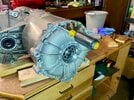
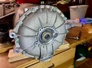
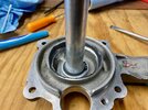
On borescope inspection, loosely assembled my disassembled motor end plate. I think the reluctor wheel doesn't provide much spacing. May need medical grade endoscopes with very narrow diameters and a short non bendable tip to make the turn and squeeze in between the wheel and the wall. Here is a pic. Speed sensor hole is ~27mm diameter and my reluctor wheel isn't mounted on the shaft so clearance is not accurate. But I'd imagine properly installed yields very little space. Really too bad, would have provide a great way to look at health of seal and bearing...
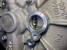
Last edited:
LD rebuild update
Primary shaft bearings (6207/6208)
- 6207 is the counter bore bearing on inverter side of gearbox half
- 6208 is the bearing on the primary shaft pressed in and locked down by a lock nut.
My 6207 was stuck in the bore. @asavage was kind enough to make a slide hammer puller tip cut out of unistrut piece. Bearing sit raised about 1/4" above the bottom of the bore so tool's lip can get under the bearing with ease. Just went around ID circumference with slide hammer and came out. Wasn't too hard. The reason it was stuck is because the outer race has surface damage where it mates with the bore. Don't know why. Could be there on the rebuild, could be the bearing slipped in the bore? Don't know. New 6207 drops right into the bore at room temp. @asavage suggest to use locktite retaining compound installing the new bearing. Will update later.
Can also purchase blind bearing puller set but need one with a 35mm collet. Amazon has cheap set for $50+. Probably work fine as 6207 normally comes out by hand if didn't have the race damage like mine. I purchased a motion pro 35mm collet. Unfortunately it uses custom slide hammer threads.
Here is the pic of the slide hammer puller and damaged bearing outer race under microscope.
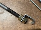

Changing 6208 is much more challenging for newbie to pulling/mounting bearings (like me! haha)
First remove the locknut and mine had red lock-tite applied. The locknut dimensions is exact (maybe 1mm thinner?) SKF lock nut. Luckily for me again, tool loving @asavage ordered a SKF socket (none of local auto store spindle sockets fit, close but no fit) and impact gun took the nut off easily just holding the shaft in hand.
Tesla Large Drive Unit (LDU) Motor Teardown and maintenance - Page 10 - openinverter forum
SKF socket is $100. SKF also has a hook spanner wrench for ~$25 (HN7 Hook spanners HN series | SKF) so might consider ordering that along with the SKF bearings. However, probably need a good vice to clamp down the shaft and maybe a cheater bar to remove with hook spanner.
Finally, some people clamp down the shaft and tap the nut loose via the notches. Again, would need a heavy duty vice. Normal right hand threads.
Pulled the bearing with a bearing splitter/puller. Clean off all remaining lock-tite on the lock-nut threads (I actually didn't do until after mounting the new bearing, mistake... read below)
Hammered the new bearing in via inner race with a 1-5/8 12pt socket. But realized afterwards the bearing puller could have been setup to press in the bearing. A couple of notes
- Its an open cage bearing so all the debris can drop into the bearing causing roughness (happened to me). Probably would have been a good idea to tape up the bearing opening facing upwards. Have all lock-tite cleaned off before installing (I didn't) and tape the locknut threads (1-5/8 socket chipped a couple of spots) All this junk went into the new bearing. Took me a awhile with compressed air to get it all out and bearing spinning smooth again. When peeling off the protection, probably turn it upside down so all debris drops to floor rather than into the bearing. Probably won't be able to see the debris but if it goes inside the bearing, you surely can feel it. Here is a pic of the slight thread damage from the 12pt socket. Perhaps 1.5" galvanized pipe (~42mm ID, 6208 ID is 40mm) would have been better (get one cut without the sharp threaded end)
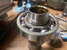
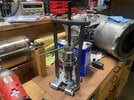
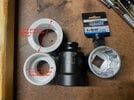
For those with machine shop skills, probably not too challenging. For a bearing newbie like me... quite the task. Perhaps worth doing some kind for mail-in service for the LDU rebuild community in the future (ship the shaft, get it back with new bearing, maybe additional kit/parts) if I can get comfortable with USPS not losing the shaft! Probably can't easily replace it.
Axle Seal
These hammered out easily and back in using a rubber mallet with the 2 cheap 2"x1-1/2" PVC pipe adapters shown above. Took the inverter (and 2 temp sensor) off to prepare for slide hammering out the stuck 6207 bearing above. Probably didn't need to as it came out with ease.
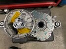
Gearbox Seal
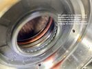
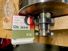
Ordered 3 Ceimin gearbox seals. 1 was defective but came with nice QC paper work for show. Ceimin seal looks like a good attempt at copying Tesla's seal. Unlikely OEM. Decided to just keep my 32k mile reman gearbox seal. Presumably it was replaced during reman.
Wiped off grease/mud inside of seal lips which seems be in wavy pattern. My gearbox has metallic mud so perhaps these were magnetic field lines from the AC motor?
Coolant Seal Shaft Surface Prep
Followed Johan's 600 grit -> 1500 grit sanding process.
- Shaft had white cloudy layer just outside of the single lip seal mating region (maybe oxidized coolant particulates?). Wouldn't come off with acetone. 600 grit took it off quickly.
- 600 grit sand paper likes to run axially on the shaft so good to have 2 people (1 to spin rotor, 1 to hold sand paper firmly with both hands)
- The lines made by original seal lip will not be completely removed. Likely too deep and require removing quite a bit of material. This line from the original single lip seal will be under the middle lip of a triple lip seal.
- Decided to sand the whole shaft where triple lip seal will sit as resurfacing the white debris and original seal surface is already about 1/2 of the surface area.
- As for how long to sand, not sure there is a right answer. I probably did 1min total on 600 grit and 1min total on 1500. 600 will already make shaft quite shiny and 1500 won't have any visible difference. So really can only go by timing on 1500 grit.
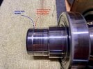
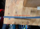
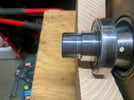
Hopefully this prep won't leak with the Ceimin triple lip PTFE seal. We shall see...
Rotor and Stator Flash Rusts
Mine had some rusts from the coolant leak. During the clean up, a protective coating is easily removed and get flash rusting. Used acetone on the rotor and got flash rust afterwards. Used denatured alcohol on parts of stator and got flash rust afterwards. Anyway, might apply a light coat of oil or WD40 after cleaning up the surfaces. If no rust to deal with, perhaps just air blow out any dust.
Thought about coating it with light spray of high temp clear coat but don't really know if its a good idea. Probably want to avoid unbalancing the rotor.
Primary shaft bearings (6207/6208)
- 6207 is the counter bore bearing on inverter side of gearbox half
- 6208 is the bearing on the primary shaft pressed in and locked down by a lock nut.
My 6207 was stuck in the bore. @asavage was kind enough to make a slide hammer puller tip cut out of unistrut piece. Bearing sit raised about 1/4" above the bottom of the bore so tool's lip can get under the bearing with ease. Just went around ID circumference with slide hammer and came out. Wasn't too hard. The reason it was stuck is because the outer race has surface damage where it mates with the bore. Don't know why. Could be there on the rebuild, could be the bearing slipped in the bore? Don't know. New 6207 drops right into the bore at room temp. @asavage suggest to use locktite retaining compound installing the new bearing. Will update later.
Can also purchase blind bearing puller set but need one with a 35mm collet. Amazon has cheap set for $50+. Probably work fine as 6207 normally comes out by hand if didn't have the race damage like mine. I purchased a motion pro 35mm collet. Unfortunately it uses custom slide hammer threads.
Here is the pic of the slide hammer puller and damaged bearing outer race under microscope.


Changing 6208 is much more challenging for newbie to pulling/mounting bearings (like me! haha)
First remove the locknut and mine had red lock-tite applied. The locknut dimensions is exact (maybe 1mm thinner?) SKF lock nut. Luckily for me again, tool loving @asavage ordered a SKF socket (none of local auto store spindle sockets fit, close but no fit) and impact gun took the nut off easily just holding the shaft in hand.
Tesla Large Drive Unit (LDU) Motor Teardown and maintenance - Page 10 - openinverter forum
SKF socket is $100. SKF also has a hook spanner wrench for ~$25 (HN7 Hook spanners HN series | SKF) so might consider ordering that along with the SKF bearings. However, probably need a good vice to clamp down the shaft and maybe a cheater bar to remove with hook spanner.
Finally, some people clamp down the shaft and tap the nut loose via the notches. Again, would need a heavy duty vice. Normal right hand threads.
Pulled the bearing with a bearing splitter/puller. Clean off all remaining lock-tite on the lock-nut threads (I actually didn't do until after mounting the new bearing, mistake... read below)
Hammered the new bearing in via inner race with a 1-5/8 12pt socket. But realized afterwards the bearing puller could have been setup to press in the bearing. A couple of notes
- Its an open cage bearing so all the debris can drop into the bearing causing roughness (happened to me). Probably would have been a good idea to tape up the bearing opening facing upwards. Have all lock-tite cleaned off before installing (I didn't) and tape the locknut threads (1-5/8 socket chipped a couple of spots) All this junk went into the new bearing. Took me a awhile with compressed air to get it all out and bearing spinning smooth again. When peeling off the protection, probably turn it upside down so all debris drops to floor rather than into the bearing. Probably won't be able to see the debris but if it goes inside the bearing, you surely can feel it. Here is a pic of the slight thread damage from the 12pt socket. Perhaps 1.5" galvanized pipe (~42mm ID, 6208 ID is 40mm) would have been better (get one cut without the sharp threaded end)


For those with machine shop skills, probably not too challenging. For a bearing newbie like me... quite the task. Perhaps worth doing some kind for mail-in service for the LDU rebuild community in the future (ship the shaft, get it back with new bearing, maybe additional kit/parts) if I can get comfortable with USPS not losing the shaft! Probably can't easily replace it.
Axle Seal
These hammered out easily and back in using a rubber mallet with the 2 cheap 2"x1-1/2" PVC pipe adapters shown above. Took the inverter (and 2 temp sensor) off to prepare for slide hammering out the stuck 6207 bearing above. Probably didn't need to as it came out with ease.

Gearbox Seal
Ordered 3 Ceimin gearbox seals. 1 was defective but came with nice QC paper work for show. Ceimin seal looks like a good attempt at copying Tesla's seal. Unlikely OEM. Decided to just keep my 32k mile reman gearbox seal. Presumably it was replaced during reman.
Wiped off grease/mud inside of seal lips which seems be in wavy pattern. My gearbox has metallic mud so perhaps these were magnetic field lines from the AC motor?

Coolant Seal Shaft Surface Prep
Followed Johan's 600 grit -> 1500 grit sanding process.
- Shaft had white cloudy layer just outside of the single lip seal mating region (maybe oxidized coolant particulates?). Wouldn't come off with acetone. 600 grit took it off quickly.
- 600 grit sand paper likes to run axially on the shaft so good to have 2 people (1 to spin rotor, 1 to hold sand paper firmly with both hands)
- The lines made by original seal lip will not be completely removed. Likely too deep and require removing quite a bit of material. This line from the original single lip seal will be under the middle lip of a triple lip seal.
- Decided to sand the whole shaft where triple lip seal will sit as resurfacing the white debris and original seal surface is already about 1/2 of the surface area.
- As for how long to sand, not sure there is a right answer. I probably did 1min total on 600 grit and 1min total on 1500. 600 will already make shaft quite shiny and 1500 won't have any visible difference. So really can only go by timing on 1500 grit.


Hopefully this prep won't leak with the Ceimin triple lip PTFE seal. We shall see...
Rotor and Stator Flash Rusts
Mine had some rusts from the coolant leak. During the clean up, a protective coating is easily removed and get flash rusting. Used acetone on the rotor and got flash rust afterwards. Used denatured alcohol on parts of stator and got flash rust afterwards. Anyway, might apply a light coat of oil or WD40 after cleaning up the surfaces. If no rust to deal with, perhaps just air blow out any dust.
Thought about coating it with light spray of high temp clear coat but don't really know if its a good idea. Probably want to avoid unbalancing the rotor.
Last edited:
another great post. if possible please include skf part for socket- another expensive but necessary tool. its quite the task for a non machinist. i dont have a lot of experience pressing in bearings. sounds like i will need help the first time too when my du goes.LD rebuild update
Primary shaft bearings (6207/6208)
- 6207 is the counter bore bearing on inverter side of gearbox half
- 6208 is the bearing on the primary shaft pressed in and locked down by a lock nut.
My 6207 was stuck in the bore. @asavage was kind enough to make a slide hammer puller tip cut out of unistrut piece. Bearing sit raised about 1/4" above the bottom of the bore so tool's lip can get under the bearing with ease. Just went around ID circumference with slide hammer and came out. Wasn't too hard. The reason it was stuck is because the outer race has surface damage where it mates with the bore. Don't know why. Could be there on the rebuild, could be the bearing slipped in the bore? Don't know. New 6207 drops right into the bore at room temp. @asavage suggest to use locktite retaining compound installing the new bearing. Will update later.
Can also purchase blind bearing puller set but need one with a 35mm collet. Amazon has cheap set for $50+. Probably work fine as 6207 normally comes out by hand if didn't have the race damage like mine. I purchased a motion pro 35mm collet. Unfortunately it uses custom slide hammer threads.
Here is the pic of the slide hammer puller and damaged bearing outer race under microscope.
View attachment 865253View attachment 865254
Changing 6208 is much more challenging for newbie to pulling/mounting bearings (like me! haha)
First remove the locknut and mine had red lock-tite applied. The locknut dimensions is exact (maybe 1mm thinner?) SKF lock nut. Luckily for me again, tool loving @asavage ordered a SKF socket (none of local auto store spindle sockets fit, close but no fit) and impact gun took the nut off easily just holding the shaft in hand.
Tesla Large Drive Unit (LDU) Motor Teardown and maintenance - Page 10 - openinverter forum
SKF socket is $100. SKF also has a hook spanner wrench for ~$25 (HN7 Hook spanners HN series | SKF) so might consider ordering that along with the SKF bearings. However, probably need a good vice to clamp down the shaft and maybe a cheater bar to remove with hook spanner.
Finally, some people clamp down the shaft and tap the nut loose via the notches. Again, would need a heavy duty vice. Normal right hand threads.
Pulled the bearing with a bearing splitter/puller. Clean off all remaining lock-tite on the lock-nut threads (I actually didn't do until after mounting the new bearing, mistake... read below)
Hammered the new bearing in via inner race with a 1-5/8 12pt socket. But realized afterwards the bearing puller could have been setup to press in the bearing. A couple of notes
- Its an open cage bearing so all the debris can drop into the bearing causing roughness (happened to me). Probably would have been a good idea to tape up the bearing opening facing upwards. Have all lock-tite cleaned off before installing (I didn't) and tape the locknut threads (1-5/8 socket chipped a couple of spots) All this junk went into the new bearing. Took me a awhile with compressed air to get it all out and bearing spinning smooth again. When peeling off the protection, probably turn it upside down so all debris drops to floor rather than into the bearing. Probably won't be able to see the debris but if it goes inside the bearing, you surely can feel it. Here is a pic of the slight thread damage from the 12pt socket. Perhaps 1.5" galvanized pipe (~42mm ID, 6208 ID is 40mm) would have been better (get one cut without the sharp threaded end)
View attachment 865266View attachment 865269View attachment 865271
For those with machine shop skills, probably not too challenging. For a bearing newbie like me... quite the task. Perhaps worth doing some kind for mail-in service for the LDU rebuild community in the future (ship the shaft, get it back with new bearing, maybe additional kit/parts) if I can get comfortable with USPS not losing the shaft! Probably can't easily replace it.
Axle Seal
These hammered out easily and back in using a rubber mallet with the 2 cheap 2"x1-1/2" PVC pipe adapters shown above. Took the inverter (and 2 temp sensor) off to prepare for slide hammering out the stuck 6207 bearing above. Probably didn't need to as it came out with ease.
View attachment 865281
Gearbox Seal
Ordered 3 Ceimin gearbox seals. 1 was defective but came with nice QC paper work for show. Ceimin seal looks like a good attempt at copying Tesla's seal. Unlikely OEM. Decided to just keep my 32k mile reman gearbox seal. Presumably it was replaced during reman.
Wiped off grease/mud inside of seal lips which seems be in wavy pattern. My gearbox has metallic mud so perhaps these were magnetic field lines from the AC motor?
View attachment 865273
Coolant Seal Shaft Surface Prep
Followed Johan's 600 grit -> 1500 grit sanding process.
- Shaft had white cloudy layer just outside of the single lip seal mating region (maybe oxidized coolant particulates?). Wouldn't come off with acetone. 600 grit took it off quickly.
- 600 grit sand paper likes to run axially on the shaft so good to have 2 people (1 to spin rotor, 1 to hold sand paper firmly with both hands)
- The lines made by original seal lip will not be completely removed. Likely too deep and require removing quite a bit of material. This line from the original single lip seal will be under the middle lip of a triple lip seal.
- Decided to sand the whole shaft where triple lip seal will sit as resurfacing the white debris and original seal surface is already about 1/2 of the surface area.
- As for how long to sand, not sure there is a right answer. I probably did 1min total on 600 grit and 1min total on 1500. 600 will already make shaft quite shiny and 1500 won't have any visible difference. So really can only go by timing on 1500 grit.
View attachment 865280View attachment 865288View attachment 865282
Hopefully this prep won't leak with the Ceimin triple lip PTFE seal. We shall see...
Rotor and Stator Flash Rusts
Mine had some rusts from the coolant leak. During the clean up, a protective coating is easily removed and get flash rusting. Used acetone on the rotor and got flash rust afterwards. Used denatured alcohol on parts of stator and got flash rust afterwards. Anyway, might apply a light coat of oil or WD40 after cleaning up the surfaces. If no rust to deal with, perhaps just air blow out any dust.
Thought about coating it with light spray of high temp clear coat but don't really know if its a good idea. Probably want to avoid unbalancing the rotor.
if possible please include skf part for socket- another expensive but necessary tool. its quite the task for a non machinist. i dont have a lot of experience pressing in bearings. sounds like i will need help the first time too when my du goes.
hi all PN is the openinverter link. Here again + purchase tips
Lock nut is KM 7 - Lock nuts and locking devices | SKF ( I don't think need to replace since reinstalled with good lock tite (242) but only $6 @ Acorn SKF - KM 7 - Nut - KM lock nut, with metric thread (acorn-ind.co.uk))
Socket is SKF TMFS 7 Axial lock nut sockets TMFS series | SKF ($88 @ Acorn SKF - TMFS 7 - Axial Lock Nut Sockets - Axial Lock Nut Sockets (acorn-ind.co.uk))
C Spanner is SFK HN 7 Hook spanners HN series | SKF ($25 @ Acorn SKF - HN 7 - Hook spanner - Hook spanner (acorn-ind.co.uk))
Best place and price to buy these is with the ceramic bearings from European sources. Acorn in UK is best price I found on SKFs and SKF listed as genuine distributor. Ceramic bearings is $109/ea, 6207 was $6 6208 was $9. $30 2-3 day DHL international shipping if in stock.
Best solution would be mail order 6208 bearing replacement as noted above. It would removes a more difficult step for the less confident with these steps and skip the investment in a couple of tools. Probably can do the coolant seal removal/install and motor end plate drain mods all at the same time with USPS priority mail large package (70lb max 2-3 days $20 each way within US) since all these pieces fits in the box and under weight limit. Return shipping could also include other long lead time parts and custom tools. Difficulty would be who assumes responsible if LDU leaks quickly or have gearbox noises from the mixed disassembly/mod/install effort and USPS lost package of rare irreplaceable parts.
Primary shaft bearings 2.0 (6208)
Redid 6208 due what is likely incorrect testing methodology for new bearings. Here was the test (For Rav4 EV so shaft has extra parking lock on it)
This test loads the bearing radially. The shaft is tilting the balls against opposing inner and outer raceways. With a brand new bearing (comes with very thin viscosity factory environmental protectant) it has no lubrication so it will not behave like a used bearing that has done many rotations in the ATF.
I dabbed some ATF on to the bearing. This made it even worse. Above test feels like there is particles inside the bearing. Even dunking the bearing in ATF didn't help (maybe overnight would?) I reasoned it wasn't possible to exchange all factory protectant with ATF without many rotations so can't load the bearing radially like this test.
Bearing otherwise spins smoothly on the shaft (hold shaft, spin bearing, not the other way around like above test) Soaking in ATF reduced the radial play of the new bearing as thicker viscosity ATF reduced internal air gap clearance.
Prior conclusion debris caused this due to open unsealed bearing is probably incorrect. Roughness is probably due to frictional difference between ATF and factory shipping protection when loading radially like this.
Shop Press
Decided to buy and use a shop press on 2nd attempt since didn't know if hammering in the bearing caused the above issue. Press is much easier and controlled but cost $250 of course. Harbor Freight 20ton has welded H frame and quite sturdy. 12 ton looked too small for the big tall rotor and its bearings. Also 12 ton H frame was bolted so probably has more play.
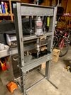
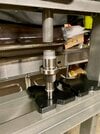
Socket used for pressing is in this post #47 which also shows a bearing splitter/puller method to install as well
TIghtening the Lock Nut
Used an impact wrench to tight the 6208 lock nut previously and bearing rattled like crazy after. Some say its okey but I lost confidence worrying the impacts could have damage the rivets in the ball cage. So tightened by hand on a vice (wood pieces to avoid marring the shaft) and SKF hook wrench (HN7) Worked great. Have a clean thread free of old locktite and oil of course along with new 242 locktite.
Installing 6207
6207's outer race probably spins in its bore judging from a couple of data points
- My old one had damage consistent with spun bearing (2nd pic DIY Tesla Drive Unit Repair)
- Some LDUs have 6207 installed with retaining compound. Here is a pic of Rev R Sport LDU removed 6207
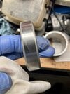
Note Rav4 EV maybe different as they run the motor in reverse and may have different loading in the gearbox. @vanR Rav4 EV had no issue removing this bearing.
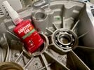
Installing with retaining compound for a bearing newbie is quite tricky. Retaining compound (locktite 648) has 3min cure window in anaerobic conditions so everything has to go perfect or will need to pull this bearing out again (which may damage it pulling by inner race) What I did was the following steps
- Clean 6207 outer race free of oil (acetone) and put in freezer for couple of hours
- When ready to install, clean the bore free of oil (acetone). Apply thin coat of 648 by finger. 648 tends to want to pool down towards the bottom. I wiped off the pools on the bottom bore edge and just applied thin coating on the bore walls. Avoid the oil feed region.
- Take 6207 out of freezer. quickly clean outer race once again with acetone. Insert the bearing into the bore before it warms up. 6207 dropped down slightly slower than freefall as it squeegies the 648 towards the bottom as it dropped. Hopefully enough remained to prevent the outer race from spinning.
- Not necessary but I used the press against outer race to make sure bearing was seated fully (it was)
A few tips and cautions
- lubricated 6207 and bore will generally go in fairly easily. Sometimes rotating the bearing can find a sweet spot. All of this ease of insertion is gone once you clean off the surface for 648. Furthermore, 648 itself adds material so its likely the bearing will no longer insert at room temperature. Just beware the bearing that use to go in so easily with lubrication will likely jam at room temp. Freezer or a press are possible solutions.
- You might order > 1 6207 in case first attempt fails. But also need method to remove stuck bearing.
- Might skip this all together if uncomfortable with the not so forgiving process. My first one screwed up at room temp, did't finger spread 648 so mostly pooled towards bottom, bearing actually went in, pulled it out to add more 648 along the walls. Next try jammed, try tapping in, was not successful, pulled bearing by inner race and didn't trust it wasn't damaged.
- A lot of videos shows how to apply 648 of a bearing on to a shaft which is much much easier. Can slob on the 648. Squeegeed off 648 just get cleaned off the shaft. Doing this in a bore is trickier. @asavage suggest can wash off the excess but its way beyond my skill set.
Finally... success (I hope) we'll see once car LDU is back in the car
Redid 6208 due what is likely incorrect testing methodology for new bearings. Here was the test (For Rav4 EV so shaft has extra parking lock on it)
This test loads the bearing radially. The shaft is tilting the balls against opposing inner and outer raceways. With a brand new bearing (comes with very thin viscosity factory environmental protectant) it has no lubrication so it will not behave like a used bearing that has done many rotations in the ATF.
I dabbed some ATF on to the bearing. This made it even worse. Above test feels like there is particles inside the bearing. Even dunking the bearing in ATF didn't help (maybe overnight would?) I reasoned it wasn't possible to exchange all factory protectant with ATF without many rotations so can't load the bearing radially like this test.
Bearing otherwise spins smoothly on the shaft (hold shaft, spin bearing, not the other way around like above test) Soaking in ATF reduced the radial play of the new bearing as thicker viscosity ATF reduced internal air gap clearance.
Prior conclusion debris caused this due to open unsealed bearing is probably incorrect. Roughness is probably due to frictional difference between ATF and factory shipping protection when loading radially like this.
Shop Press
Decided to buy and use a shop press on 2nd attempt since didn't know if hammering in the bearing caused the above issue. Press is much easier and controlled but cost $250 of course. Harbor Freight 20ton has welded H frame and quite sturdy. 12 ton looked too small for the big tall rotor and its bearings. Also 12 ton H frame was bolted so probably has more play.


Socket used for pressing is in this post #47 which also shows a bearing splitter/puller method to install as well
TIghtening the Lock Nut
Used an impact wrench to tight the 6208 lock nut previously and bearing rattled like crazy after. Some say its okey but I lost confidence worrying the impacts could have damage the rivets in the ball cage. So tightened by hand on a vice (wood pieces to avoid marring the shaft) and SKF hook wrench (HN7) Worked great. Have a clean thread free of old locktite and oil of course along with new 242 locktite.
Installing 6207
6207's outer race probably spins in its bore judging from a couple of data points
- My old one had damage consistent with spun bearing (2nd pic DIY Tesla Drive Unit Repair)
- Some LDUs have 6207 installed with retaining compound. Here is a pic of Rev R Sport LDU removed 6207

Note Rav4 EV maybe different as they run the motor in reverse and may have different loading in the gearbox. @vanR Rav4 EV had no issue removing this bearing.
Installing with retaining compound for a bearing newbie is quite tricky. Retaining compound (locktite 648) has 3min cure window in anaerobic conditions so everything has to go perfect or will need to pull this bearing out again (which may damage it pulling by inner race) What I did was the following steps
- Clean 6207 outer race free of oil (acetone) and put in freezer for couple of hours
- When ready to install, clean the bore free of oil (acetone). Apply thin coat of 648 by finger. 648 tends to want to pool down towards the bottom. I wiped off the pools on the bottom bore edge and just applied thin coating on the bore walls. Avoid the oil feed region.
- Take 6207 out of freezer. quickly clean outer race once again with acetone. Insert the bearing into the bore before it warms up. 6207 dropped down slightly slower than freefall as it squeegies the 648 towards the bottom as it dropped. Hopefully enough remained to prevent the outer race from spinning.
- Not necessary but I used the press against outer race to make sure bearing was seated fully (it was)
A few tips and cautions
- lubricated 6207 and bore will generally go in fairly easily. Sometimes rotating the bearing can find a sweet spot. All of this ease of insertion is gone once you clean off the surface for 648. Furthermore, 648 itself adds material so its likely the bearing will no longer insert at room temperature. Just beware the bearing that use to go in so easily with lubrication will likely jam at room temp. Freezer or a press are possible solutions.
- You might order > 1 6207 in case first attempt fails. But also need method to remove stuck bearing.
- Might skip this all together if uncomfortable with the not so forgiving process. My first one screwed up at room temp, did't finger spread 648 so mostly pooled towards bottom, bearing actually went in, pulled it out to add more 648 along the walls. Next try jammed, try tapping in, was not successful, pulled bearing by inner race and didn't trust it wasn't damaged.
- A lot of videos shows how to apply 648 of a bearing on to a shaft which is much much easier. Can slob on the 648. Squeegeed off 648 just get cleaned off the shaft. Doing this in a bore is trickier. @asavage suggest can wash off the excess but its way beyond my skill set.
Finally... success (I hope) we'll see once car LDU is back in the car

Last edited:
Removing Inverter
Inverter was removed for safety prior to pulling the 6207 with a slide hammer. 6207 came out easily so inverter removal wasn't necessary. Inverter reinstall isn't so easy and3-5 coolant passages with o-rings are opened up. Should avoid unless its necessary.
Remove the top plate
- Remove purple arrow torx bolts
- Remove yellow arrow torx bolts. Dash yellow bolt is tucked under and hard to reach. Finally got it loose with with torx driver at an angle. Careful to not strip the bolt. Alternative is to cut a torx bit down to size and use it with a small wrench. Yet another alternative is to remove the 4 brown arrow bolts. These bolts provide top structure for the 3 phase plates so I didn't touch these (bottom of the phase plate is also bolted together for structural support)
- Disconnect green arrow connector
- Another connector underneath after top plate is loose
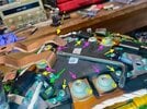
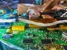
- Dashed yellow arrow bolt can be replaced with hex for ease of reassembly and future removal.
Disconnect temp sensor
- Yellow arrow temp sensor connector was removed to split the gearbox into 2 halves in post #35
- Disconnect purple arrow temp sensor connector
- Disconnect green arrow temp sensor connector
- Cut red arrow zip tie for temp sensor wire (already cut and missing in pic)
- Route green arrow temp sensor white wire out of the way. It routes to the other side of the inverter to the temp sensor
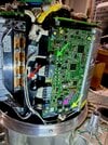
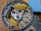
Disconnect 3 phase plates
- Remove all 3 sets of 5 torx bolts (purple arrow). One set per phase. Apologize for blurry pic as camera focused on nearer item. Good to have a long tool (yellow arrow) to grab the bolts deep inside the triangular cavern.
- Pull up by metal columns (green arrow) which is also used to place the inverter down horizontally. Inverter is somewhat heavy but awkward holding by the metal columns.
- Need to clear the blue bus bar tunnel extrusion. Then inverter is completely freed.
- Remove and store the 3x square o-rings (pic above shows their slots but o-ring already removed) Its quite difficult to put the inverter back on while repositioning lining up the 3x5 bolt holes and not lift and damage the o-ring (how to in next post)
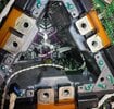
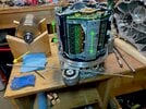
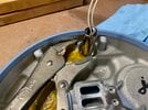
Removing Temp Sensor (if necessary)
Short wire one comes out easy with 14mm wrench. Long wire one need a fancy wrench or a tall 14mm socket and vice grip to turn the socket.
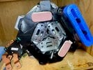
Inverter was removed for safety prior to pulling the 6207 with a slide hammer. 6207 came out easily so inverter removal wasn't necessary. Inverter reinstall isn't so easy and3-5 coolant passages with o-rings are opened up. Should avoid unless its necessary.
Remove the top plate
- Remove purple arrow torx bolts
- Remove yellow arrow torx bolts. Dash yellow bolt is tucked under and hard to reach. Finally got it loose with with torx driver at an angle. Careful to not strip the bolt. Alternative is to cut a torx bit down to size and use it with a small wrench. Yet another alternative is to remove the 4 brown arrow bolts. These bolts provide top structure for the 3 phase plates so I didn't touch these (bottom of the phase plate is also bolted together for structural support)
- Disconnect green arrow connector
- Another connector underneath after top plate is loose


- Dashed yellow arrow bolt can be replaced with hex for ease of reassembly and future removal.
Disconnect temp sensor
- Yellow arrow temp sensor connector was removed to split the gearbox into 2 halves in post #35
- Disconnect purple arrow temp sensor connector
- Disconnect green arrow temp sensor connector
- Cut red arrow zip tie for temp sensor wire (already cut and missing in pic)
- Route green arrow temp sensor white wire out of the way. It routes to the other side of the inverter to the temp sensor


Disconnect 3 phase plates
- Remove all 3 sets of 5 torx bolts (purple arrow). One set per phase. Apologize for blurry pic as camera focused on nearer item. Good to have a long tool (yellow arrow) to grab the bolts deep inside the triangular cavern.
- Pull up by metal columns (green arrow) which is also used to place the inverter down horizontally. Inverter is somewhat heavy but awkward holding by the metal columns.
- Need to clear the blue bus bar tunnel extrusion. Then inverter is completely freed.
- Remove and store the 3x square o-rings (pic above shows their slots but o-ring already removed) Its quite difficult to put the inverter back on while repositioning lining up the 3x5 bolt holes and not lift and damage the o-ring (how to in next post)


Removing Temp Sensor (if necessary)
Short wire one comes out easy with 14mm wrench. Long wire one need a fancy wrench or a tall 14mm socket and vice grip to turn the socket.

Reinstalling Inverter
- 2 people is really helpful for this
- Insert o-ring
- 3x M6x1.0 threaded shaft (Ace Hardware near me) can be used for alignment guide
- 2x wood piece to hold inverter after lowering inverter through the alignment guide
- check o-rings are all seated and ready for final drop
- Have 2nd person remove wood piece. Then drop the inverter over the o-ring. Blue bus bar extrusion can get caught so carefully guide it down
- 3x5 torx bolts are ~5nm?
- Reinstall top plate. Maybe replace difficult to reach torx bolt with hex equivalent.
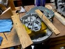
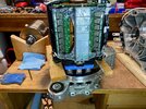
If you damaged the o-ring during install with repeated repositioning and end up with a leak. Can use following o-ring as substitute.
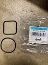
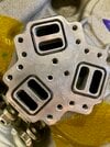
- 2 people is really helpful for this
- Insert o-ring
- 3x M6x1.0 threaded shaft (Ace Hardware near me) can be used for alignment guide
- 2x wood piece to hold inverter after lowering inverter through the alignment guide
- check o-rings are all seated and ready for final drop
- Have 2nd person remove wood piece. Then drop the inverter over the o-ring. Blue bus bar extrusion can get caught so carefully guide it down
- 3x5 torx bolts are ~5nm?
- Reinstall top plate. Maybe replace difficult to reach torx bolt with hex equivalent.


If you damaged the o-ring during install with repeated repositioning and end up with a leak. Can use following o-ring as substitute.


Removing Installing Rotor Bearings
Bearing splitter/puller
Best avoid impact gun to turn the bearing splitter/puller to remove the bearing and do it by hand. These pullers tend to shift around during pulling. The splitter can easily nick the bearing stop. If get a nick, check to make sure bearing stop is flat all the way around the shaft.
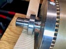
Rotor Bearing Inner Diameter
35mm
1-1/4" PVC pipe
ID is slightly less than 35mm ID of rotor bearings. Can enlarge slightly with Dremel tool. This is what I used to hammer in the bearing with rotor laying flat axially on the work table. Took quite a bit of force with a 2+lb hammer with maybe 5-10 strikes as PVC pipe acts like a damper. Marked F in pics below (with an end cap for hammering)
1-1/4" Galvanized Pipe
May want to consult someone with bearing expertise on what type of hammer (plastic/soft faced hammer?) to use with galvanized pipe to drive in bearing inner race. Not an issue if using a press.
ID is generally just above 35mm but some are < 35mm. Take caliper to measure both ends.
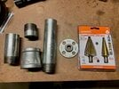
A 12" 1-1/4" Galvanized Pipe threaded on both ends can be cut into 3 useful pieces
- First cut 1/2" from end of thread
- 2nd cut 3.5" from first cut. Cut thread to one end (make sure thread cutter goes all the way through as these are tapered threads) Threads are useful to pair with an adapter (see below) for a wider base stand.
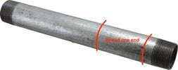
The resulting pieces are C/D/E. Cut pipe end need to be reamed. Hardware store cutting tool can not ream the shortest piece. And the reaming tip can be wide angled which thins out the end when reamed (pic below is a narrow angle reaming tip. I had one that was ~90 deg angled tip) Use a stepped drill bit able to do 1-3/8 to ream the pipe away from your disassembled LDU parts as shards will go everywhere. May want to cover up your gears/bearings/gearbox casing/inverter.
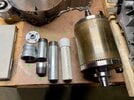
Buy a 1-1/4" to 1-1/2" adapter (B in pic, not so commonly available, found in 1 of 4 hardware stores near me).
- D can be used to press/tap in bearing on coolant opening end of the rotor shaft. C+B can be a stand on the other end
- C can be used to press/tap in bearing on the spline end of the rotor shaft. D+B can be a stand on the other end
- E+B can be used to hammer/press in coolant seal. 1-1/2" opening has 50mm ID and 60+OD. Perfect to push seal into its sleeve
When standing up rotor on these pieces. Best to have a 2nd person to help with 70lb rotor standing on very narrow stands.
I haven't done it this way myself but measured and made all the pieces.
Post bearing install
Put bearing on blocks and spin to check shaft does not have axial movement during rotation. Mine had a little, not sure why. Had to hammer the bearings again to make sure seated fully to the stop. However, probably don't want to hammer bearing inner race too hard while resting on the rotor instead of standing in the other end.
Do not put the coolant opening end of the shaft on the ground and hammer/press on the shaft. Opening has a more fragile bevel edge for seal installation.
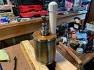
Note rotating rotor on V wood blocks need to be perfectly leveled. I had 4mm height difference on one end and bearing made random rail road track gap noise. Hollowed coolant shaft will amplify any noise. Once my rotor was leveled... basically quiet.
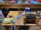
Finally, without any prior bearing experience. Have no idea if hammering the inner race with reasonable force will damage these expensive ceramic ball bearings. Press is probably preferred if can access one. A lot of people do show hammering the bearings in on youtube videos. Just note they are probably very experienced and generally with a machine shop setup.
Bearing splitter/puller
Best avoid impact gun to turn the bearing splitter/puller to remove the bearing and do it by hand. These pullers tend to shift around during pulling. The splitter can easily nick the bearing stop. If get a nick, check to make sure bearing stop is flat all the way around the shaft.

Rotor Bearing Inner Diameter
35mm
1-1/4" PVC pipe
ID is slightly less than 35mm ID of rotor bearings. Can enlarge slightly with Dremel tool. This is what I used to hammer in the bearing with rotor laying flat axially on the work table. Took quite a bit of force with a 2+lb hammer with maybe 5-10 strikes as PVC pipe acts like a damper. Marked F in pics below (with an end cap for hammering)
1-1/4" Galvanized Pipe
May want to consult someone with bearing expertise on what type of hammer (plastic/soft faced hammer?) to use with galvanized pipe to drive in bearing inner race. Not an issue if using a press.
ID is generally just above 35mm but some are < 35mm. Take caliper to measure both ends.
A 12" 1-1/4" Galvanized Pipe threaded on both ends can be cut into 3 useful pieces
- First cut 1/2" from end of thread
- 2nd cut 3.5" from first cut. Cut thread to one end (make sure thread cutter goes all the way through as these are tapered threads) Threads are useful to pair with an adapter (see below) for a wider base stand.

The resulting pieces are C/D/E. Cut pipe end need to be reamed. Hardware store cutting tool can not ream the shortest piece. And the reaming tip can be wide angled which thins out the end when reamed (pic below is a narrow angle reaming tip. I had one that was ~90 deg angled tip) Use a stepped drill bit able to do 1-3/8 to ream the pipe away from your disassembled LDU parts as shards will go everywhere. May want to cover up your gears/bearings/gearbox casing/inverter.

Buy a 1-1/4" to 1-1/2" adapter (B in pic, not so commonly available, found in 1 of 4 hardware stores near me).
- D can be used to press/tap in bearing on coolant opening end of the rotor shaft. C+B can be a stand on the other end
- C can be used to press/tap in bearing on the spline end of the rotor shaft. D+B can be a stand on the other end
- E+B can be used to hammer/press in coolant seal. 1-1/2" opening has 50mm ID and 60+OD. Perfect to push seal into its sleeve
When standing up rotor on these pieces. Best to have a 2nd person to help with 70lb rotor standing on very narrow stands.
I haven't done it this way myself but measured and made all the pieces.


Post bearing install
Put bearing on blocks and spin to check shaft does not have axial movement during rotation. Mine had a little, not sure why. Had to hammer the bearings again to make sure seated fully to the stop. However, probably don't want to hammer bearing inner race too hard while resting on the rotor instead of standing in the other end.
Do not put the coolant opening end of the shaft on the ground and hammer/press on the shaft. Opening has a more fragile bevel edge for seal installation.

Note rotating rotor on V wood blocks need to be perfectly leveled. I had 4mm height difference on one end and bearing made random rail road track gap noise. Hollowed coolant shaft will amplify any noise. Once my rotor was leveled... basically quiet.

Finally, without any prior bearing experience. Have no idea if hammering the inner race with reasonable force will damage these expensive ceramic ball bearings. Press is probably preferred if can access one. A lot of people do show hammering the bearings in on youtube videos. Just note they are probably very experienced and generally with a machine shop setup.
Last edited:
Caution on Pressing Rotor Bearings on Shop Press
This might be somewhat dangerous with 70lb weight sitting vertically on a narrow 1-1/4" tube on a narrow press platform without a locked down anvil while a couple of feet off the ground. Best work with someone know how to setup a shop press safely to try this.
Could also have the rotor itself sit on the press shelf with shaft extend downwards if clearance allows. Just need to stop applying press pressure once reach stop and not push further on the shaft.
Perhaps just easier to hammer the bearing in if you are comfortable with that
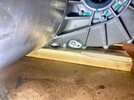
Final Inverter Bolt under bus bar
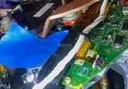
Filed down 4 sides to was pretty easy to use with a wrench. Metal was soft and filed flat quickly with bolt in a vise. Block the big opening next to it in case it drops into the triangle cavern
Gear Assembly
Mostly per @vanR's video. Here is a couple of additional tips
Freezing primary shaft (in a ziplock bag) enables it tap in fairly easily. But it isn't too hard without it either. especially on the Tesla (no need to tap in primary and intermediate shaft simultaneously like Rav4 EV) Small mallet in the picture alternating tap outer race on opposite ends got it in pretty quickly. Stop 1/2 way to check the oil seal from the rotor cavity opening to make sure it didn't fold over (also remember to coat shaft and seal surface with ATF) Freezing metal does wants to stick to your skin even with a coat of ATF on it. Need to watch the oil seal lip carefully to make sure it doesn't stick.
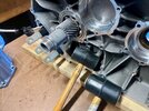
Oil pump gear clip was slightly bent due to the differential gear loading the oil pump gear against the clip. Straighten it out but probably will bend soon again. There was red loctite on my clip and mating surface on the plastic gear. Probably didn't achieve anything.
Assembling Gearbox Halves Part 1
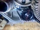
Threading the wire between the 2 halves
Threading the wire through bus bar tunnel is very challenging without a plastic braided sleeve (1/4" from amazon) The white rubbery wire protection wants to grab onto everything. With braided sleeve covering the entire wire, the original short braid segment can be discarded.
Trick is to feed the empty flat sleeve from inverter side, then put the white wire in the sleeve. Pull front of wire through the sleeve continuously and feed the sleeve further along the white wire until all the wire is covered. Then it easily pulls the white wire inside the sleeve towards the inverter. I actually didn't do it this way but realized it would be easier afterwards. Credit goes to @Wim_V on his post here
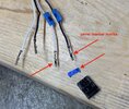
Make sure the wires are marked for which pin they go into as any taped pin # may dislodge in this process. Its 4 wires with alternating colors so just marked pin 1 and 2 along with where they go on the connector during disassembly. Don't just count on taped #s alone as they can dislodge or generally get lost in this project (Probably take 2-3 months gathering materials and waiting for shipping) Take 2 pics like below for reference for reassembly.
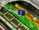
Assemble Upside Down
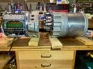
The inverter's underside has no firm support. Its the control board, wiring harness and connectors along with the fragile external connector. Heard someone manage to damage the CANBUS on the external connector so chose to assemble the gearbox upside down since inverter has a firm footing this way. However, there are downsides
- Need to be careful and not knock off the 2 breather caps. There is clearance above the 2x4 platform but need to be cautious when moving the gearbox halves and 2x4 platforms around while trying to fit the halves together.
- When finished, need to flip the big heavy combined LDU right side up
Filed down 4 sides to was pretty easy to use with a wrench. Metal was soft and filed flat quickly with bolt in a vise. Block the big opening next to it in case it drops into the triangle cavern

Gear Assembly
Mostly per @vanR's video. Here is a couple of additional tips
Freezing primary shaft (in a ziplock bag) enables it tap in fairly easily. But it isn't too hard without it either. especially on the Tesla (no need to tap in primary and intermediate shaft simultaneously like Rav4 EV) Small mallet in the picture alternating tap outer race on opposite ends got it in pretty quickly. Stop 1/2 way to check the oil seal from the rotor cavity opening to make sure it didn't fold over (also remember to coat shaft and seal surface with ATF) Freezing metal does wants to stick to your skin even with a coat of ATF on it. Need to watch the oil seal lip carefully to make sure it doesn't stick.

Oil pump gear clip was slightly bent due to the differential gear loading the oil pump gear against the clip. Straighten it out but probably will bend soon again. There was red loctite on my clip and mating surface on the plastic gear. Probably didn't achieve anything.

Assembling Gearbox Halves Part 1
Threading the wire between the 2 halves
Threading the wire through bus bar tunnel is very challenging without a plastic braided sleeve (1/4" from amazon) The white rubbery wire protection wants to grab onto everything. With braided sleeve covering the entire wire, the original short braid segment can be discarded.
Trick is to feed the empty flat sleeve from inverter side, then put the white wire in the sleeve. Pull front of wire through the sleeve continuously and feed the sleeve further along the white wire until all the wire is covered. Then it easily pulls the white wire inside the sleeve towards the inverter. I actually didn't do it this way but realized it would be easier afterwards. Credit goes to @Wim_V on his post here
Make sure the wires are marked for which pin they go into as any taped pin # may dislodge in this process. Its 4 wires with alternating colors so just marked pin 1 and 2 along with where they go on the connector during disassembly. Don't just count on taped #s alone as they can dislodge or generally get lost in this project (Probably take 2-3 months gathering materials and waiting for shipping) Take 2 pics like below for reference for reassembly.


Assemble Upside Down
The inverter's underside has no firm support. Its the control board, wiring harness and connectors along with the fragile external connector. Heard someone manage to damage the CANBUS on the external connector so chose to assemble the gearbox upside down since inverter has a firm footing this way. However, there are downsides
- Need to be careful and not knock off the 2 breather caps. There is clearance above the 2x4 platform but need to be cautious when moving the gearbox halves and 2x4 platforms around while trying to fit the halves together.
- When finished, need to flip the big heavy combined LDU right side up


Assembling the gearbox Part 2
Used a round end of a drill bit to prevent sealant from block the small round coolant passage.
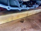
Test Fit Test Fit Test Fit
Test fit the 2 halves together... do it multiple times. And despite being heavy, go from the position where sealant would be applied to check the test fit. My test fit went well with the 2 halves close together. However, moved the inverter halve further away (more room) to apply the sealant... then it didn't fit so well after and was a struggle to fit it together with sealant on the mating surface. There is no good hold on the inverter side with the cover off to pull the white wire. Anyhow, practice multiple times. Each practice probably scrape off some ATF on the bore/shaft/bearing races making next fitting a little harder. Note the ATF coating want to drip and run towards the sealant seams so be careful and wipe off gravity pooled excess.
Applying sealant will not have a nice steady bead without toothpaste squeezer like @vanR videos. Didn't have one and was very uneven, had to spread it more evenly by fingers. Probably want to avoid making it too thin.
3 bus bars go in first, followed by repeatedly pulling the white wire slack (easy when fully wrapped in braided sleeve) while fitting the halves together. 3 shafts need to mate into their counter parts, 2 dows need to be inserted. Probably goo idea to stop as you get closer to inspect the 2 coolant o-rings and rubber string (if your LDU version has one) and check the drill bit didn't get pushed out.
Finger tight isn't really possible. I lightly snugged all the bolts with ratchet. Waited about an hour and torqued to spec.
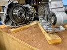
Hopefully no leaks... Test filling ATF and pump coolant through the LDU circuit per @vanR is a good idea.
Used a round end of a drill bit to prevent sealant from block the small round coolant passage.


Test Fit Test Fit Test Fit
Test fit the 2 halves together... do it multiple times. And despite being heavy, go from the position where sealant would be applied to check the test fit. My test fit went well with the 2 halves close together. However, moved the inverter halve further away (more room) to apply the sealant... then it didn't fit so well after and was a struggle to fit it together with sealant on the mating surface. There is no good hold on the inverter side with the cover off to pull the white wire. Anyhow, practice multiple times. Each practice probably scrape off some ATF on the bore/shaft/bearing races making next fitting a little harder. Note the ATF coating want to drip and run towards the sealant seams so be careful and wipe off gravity pooled excess.
Applying sealant will not have a nice steady bead without toothpaste squeezer like @vanR videos. Didn't have one and was very uneven, had to spread it more evenly by fingers. Probably want to avoid making it too thin.
3 bus bars go in first, followed by repeatedly pulling the white wire slack (easy when fully wrapped in braided sleeve) while fitting the halves together. 3 shafts need to mate into their counter parts, 2 dows need to be inserted. Probably goo idea to stop as you get closer to inspect the 2 coolant o-rings and rubber string (if your LDU version has one) and check the drill bit didn't get pushed out.
Finger tight isn't really possible. I lightly snugged all the bolts with ratchet. Waited about an hour and torqued to spec.

Hopefully no leaks... Test filling ATF and pump coolant through the LDU circuit per @vanR is a good idea.
Last edited:
Triple lip PTFE Seal
PTFE seal is hard like plastic. New PTFE seal lips out of package is 2-3+mm smaller diameter than the coolant shaft. After fitting onto the shaft. The lips will stay stretched for easy refitting but gradually shrink again within hours. Here are the tricks for proper fitting. I would guess this is an error prone step. Its quite easy to crimp/fold the excluder lip during final installation after mounted on the coolant manifold.
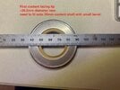
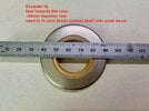
Fitting
Once installed, seal lips will not shrink back to original diameter for days. So good to do this while rotor not yet installed and have easy access. Here are the steps
- Clean the prepared shaft seal surface well (@vanR suggested acetone, works well)
- Don't try to get seal on in 1 single step. Its not possible. Have to widen the lips first. See pg1 of the attached coolant seal.pdf
- After install and removal, good to inspect the seal lips with magnifying glass to ensure no manufacturing defects.
Wait to press/drive seal into the coolant manifold
Don't do this until just before installing the coolant manifold which is basically last step of assembling the LDU. Can fit the seal again to make sure fully stretched. Press/drive seal into the manifold with sealant and put it right back on to the coolant shaft to remain stretched until ready to install the manifold.
PTFE seal is hard like plastic. New PTFE seal lips out of package is 2-3+mm smaller diameter than the coolant shaft. After fitting onto the shaft. The lips will stay stretched for easy refitting but gradually shrink again within hours. Here are the tricks for proper fitting. I would guess this is an error prone step. Its quite easy to crimp/fold the excluder lip during final installation after mounted on the coolant manifold.


Fitting
Once installed, seal lips will not shrink back to original diameter for days. So good to do this while rotor not yet installed and have easy access. Here are the steps
- Clean the prepared shaft seal surface well (@vanR suggested acetone, works well)
- Don't try to get seal on in 1 single step. Its not possible. Have to widen the lips first. See pg1 of the attached coolant seal.pdf

- After install and removal, good to inspect the seal lips with magnifying glass to ensure no manufacturing defects.
Wait to press/drive seal into the coolant manifold
Don't do this until just before installing the coolant manifold which is basically last step of assembling the LDU. Can fit the seal again to make sure fully stretched. Press/drive seal into the manifold with sealant and put it right back on to the coolant shaft to remain stretched until ready to install the manifold.
Attachments
Testing for ATF leaks after sealing gearbox
Tesla ATF capacity spec for LDU is 1.4L. Clip at end of drive shafts were removed per @vanR videos. During forward rotation, can hear the oil pump squeezing. I also inserted new primary and intermediate shaft counter bore bearings without lubricating them. Probably should have soaked them but it gets messy for installing 6207 with retaining compound (requires clean outer race) and avoid dripping ATF while sealing the gearbox with sealant. Intermediate shaft counter bore bearing rides well above the ATF line without any direct oil passages. I could hear these bearings while rotating the drive shaft. Probably quiet down quickly as car gets driven and ATF slings all over with rotating gears.
If I do this again, I'd just soak all new bearings in ATF for a day, then remove and drain before use.
Adding coolant drain on motor end plate
Installed 6mm barb with M6 x 1.0 threads ($3 for 5 on aliexpress, 2-3 weeks ship) for drain per @vanR videos. Buy an extra long 6mm x 1.0 thread tap. Had a short tap which didn't fit onto any sockets and extension. The raised fin on the endplate will push the tap the direction of the purple arrow and cause poorly tapped threads and tuck the barb under the manifold. I had to shave some materials off the coolant manifold for hose clearance.
Use silicon 3mm ID x 5mm OD hose to attach to barb (amazon $5 for 3 feet). Commonly available 0.170" ID 1/4" OD clear vinyl tubing can't hold back the coolant even tightly fitted onto the barb (seems to loosen after coolant penetrate the barb sections)
I used loctite 577 (resistant to glycol, long purchase/shipping lead time on amazon) to seal the threads. Also apply around all the gaps to seal.
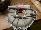
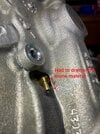
Seal off the vent hole on speed sensor chamber
Used JB Weld 2 part activated epoxy to seal off this hole to prevent agitated and aerosolized coolant from entering rotor/stator chamber. The tapped drain port will act as vent if not closed off.
Assembling rotor, endplate, reluctor wheel
This can be done on a table horizontally. Used the side of the hammer to gently tap (I tapped with no more than 3" of travel) reluctor wheel onto the coolant shaft. The reluctor wheel doesn't completely clear the bevel at its stop limit. Have a tiny extrusion over the bevel region.
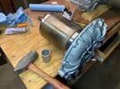
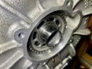
Installing Rotor and Endplate
Once rotor is in its cavity, center of gravity is quite heavy where the motor is. Make sure don't have the cavity extended very far over the edge of the table. It will want to tilt after adding 70+ pound rotor. Sit the assembly on 3 pieces of 2x4s for good all around support. May want to put all the torx head bolts on the inverter casing so its firmly attached.
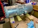
Inserting the rotor this way can be a little struggle. The ceramic bearing on the gearbox side need to slide up into its sleeve (will slide in with a little pressure). Rotor may need to turn a little to catch the splines on the primary shaft. And need to fit/tap the end plate on all while the is sealant on the mating surface (probably get some on hand and arm/long sleeve clothing). It can be difficult to handle the 70lb rotor endplate assembly without a good way to hold it other than bottom of the horizontal rotor cylinder. Use a screw driver to lever up the end plate to fit/tap into the stator housing. I applied the sealant on the stator housing side. Before final closure, check the o-ring on the bottom remained in place.
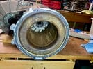
This video shows a little easier method but I didn't want to tap in the reluctor wheel while rotor was already installed with the end plate and transmit the tapping forces through the ceramic ball bearing. These videos always make it look so much easier and with less force than it really requires.

Tesla ATF capacity spec for LDU is 1.4L. Clip at end of drive shafts were removed per @vanR videos. During forward rotation, can hear the oil pump squeezing. I also inserted new primary and intermediate shaft counter bore bearings without lubricating them. Probably should have soaked them but it gets messy for installing 6207 with retaining compound (requires clean outer race) and avoid dripping ATF while sealing the gearbox with sealant. Intermediate shaft counter bore bearing rides well above the ATF line without any direct oil passages. I could hear these bearings while rotating the drive shaft. Probably quiet down quickly as car gets driven and ATF slings all over with rotating gears.
If I do this again, I'd just soak all new bearings in ATF for a day, then remove and drain before use.
Adding coolant drain on motor end plate
Installed 6mm barb with M6 x 1.0 threads ($3 for 5 on aliexpress, 2-3 weeks ship) for drain per @vanR videos. Buy an extra long 6mm x 1.0 thread tap. Had a short tap which didn't fit onto any sockets and extension. The raised fin on the endplate will push the tap the direction of the purple arrow and cause poorly tapped threads and tuck the barb under the manifold. I had to shave some materials off the coolant manifold for hose clearance.
Use silicon 3mm ID x 5mm OD hose to attach to barb (amazon $5 for 3 feet). Commonly available 0.170" ID 1/4" OD clear vinyl tubing can't hold back the coolant even tightly fitted onto the barb (seems to loosen after coolant penetrate the barb sections)
I used loctite 577 (resistant to glycol, long purchase/shipping lead time on amazon) to seal the threads. Also apply around all the gaps to seal.


Seal off the vent hole on speed sensor chamber
Used JB Weld 2 part activated epoxy to seal off this hole to prevent agitated and aerosolized coolant from entering rotor/stator chamber. The tapped drain port will act as vent if not closed off.
Assembling rotor, endplate, reluctor wheel
This can be done on a table horizontally. Used the side of the hammer to gently tap (I tapped with no more than 3" of travel) reluctor wheel onto the coolant shaft. The reluctor wheel doesn't completely clear the bevel at its stop limit. Have a tiny extrusion over the bevel region.


Installing Rotor and Endplate
Once rotor is in its cavity, center of gravity is quite heavy where the motor is. Make sure don't have the cavity extended very far over the edge of the table. It will want to tilt after adding 70+ pound rotor. Sit the assembly on 3 pieces of 2x4s for good all around support. May want to put all the torx head bolts on the inverter casing so its firmly attached.

Inserting the rotor this way can be a little struggle. The ceramic bearing on the gearbox side need to slide up into its sleeve (will slide in with a little pressure). Rotor may need to turn a little to catch the splines on the primary shaft. And need to fit/tap the end plate on all while the is sealant on the mating surface (probably get some on hand and arm/long sleeve clothing). It can be difficult to handle the 70lb rotor endplate assembly without a good way to hold it other than bottom of the horizontal rotor cylinder. Use a screw driver to lever up the end plate to fit/tap into the stator housing. I applied the sealant on the stator housing side. Before final closure, check the o-ring on the bottom remained in place.


This video shows a little easier method but I didn't want to tap in the reluctor wheel while rotor was already installed with the end plate and transmit the tapping forces through the ceramic ball bearing. These videos always make it look so much easier and with less force than it really requires.
Last edited:
Assemble the coolant manifold
First fit the triple lip PTFE seal onto the shaft again to stretch it out.
Apply sealant to inner wall of the bore for seal cage. I spread it by fingers (make sure its clean)
Ceimin triple lip seal is 8.15mm wide while the bore is 10mm deep. So there is a gap of ~2mm if seal is flush mounted to the top of the bore. pg 2 of post #57 shows ~0.5+mm of clearance on both excluder lip and coolant lip after fully assembled. Not much margin.
Pressed in the seal with cage flush to the top of the bore using the tools made in post #53 Unfortunately indented top of the coolant tube as I inverted the plate during pressing (purple arrows) So definitely check clearance before pressing as the tools will need about 10mm of clearance to top of the coolant tube. Hopefully didn't bend or crack the tube's connection to the manifold.
Insert the assembled manifold with seal onto the rotor shaft/endplate without sealant to ensure seal fits on easily. It should since the seal lips were just stretched prior to assembly. Then remove, insert o-ring onto end plate, apply sealant and fully assemble.
First fit the triple lip PTFE seal onto the shaft again to stretch it out.

Apply sealant to inner wall of the bore for seal cage. I spread it by fingers (make sure its clean)

Ceimin triple lip seal is 8.15mm wide while the bore is 10mm deep. So there is a gap of ~2mm if seal is flush mounted to the top of the bore. pg 2 of post #57 shows ~0.5+mm of clearance on both excluder lip and coolant lip after fully assembled. Not much margin.
Pressed in the seal with cage flush to the top of the bore using the tools made in post #53 Unfortunately indented top of the coolant tube as I inverted the plate during pressing (purple arrows) So definitely check clearance before pressing as the tools will need about 10mm of clearance to top of the coolant tube. Hopefully didn't bend or crack the tube's connection to the manifold.

Insert the assembled manifold with seal onto the rotor shaft/endplate without sealant to ensure seal fits on easily. It should since the seal lips were just stretched prior to assembly. Then remove, insert o-ring onto end plate, apply sealant and fully assemble.
LDU Coolant Circuit Leak Test
Drain ATF in the gearbox if haven't done so. Will need to open drain plug to check for coolant leaks.
$20 aquarium pump + 3/4" ID silicon tubing (both amazon) and 2 gallon bucket are used for coolant circuit test. Pump is silicon lubricated (says safe for fish) Ran it in the old drained coolant from LDU during removal for 5min just to clean out. Coolant circuit test ran 15min. Silicon hose crimp easily so either hold it or twist/route it for the least crimp. Pump has adjustable rate (set to ~medium) Check leak in the following areas
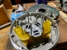
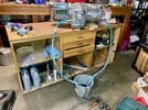
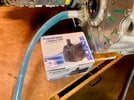
Dropping the LDU back onto the Subframe
This is quite challenging as the subframe cradles the LDU tightly with little room requiring very good alignment.
Coolant inlet and passenger side subframe mount bolts
Remove the plastic coolant inlet on the manifold. Space is really tight and can easily damage this during the drop. Not sure there is even enough space for it to clear during the drop.
Locate the 3 bolts for the driver side LDU mount. Short one has < 2mm before bottoming out during assembly. If used the long one for that hole, bolt will bottom out. Put bolts aside, just remember where the short one goes.
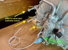
Lifting Straps and Ratchet Location
The 2 LDU mounts in front and rear of the gearbox must be leveled for the LDU to drop into the subframe. The differential/drive shaft end of the gearbox will want to tilt downwards. Place strap ratchet on this end to adjust gearbox mount level.
Straps on motor side and inverter side probably should not cross over the gearbox to the other side under the motor mount. Can't be removed after LDU drop. Also avoid pressing the straps onto wood blocks under the subframe so an be removed.
Wach the strap's clearance to the coolant tube on top of stator housing. Avoid putting pressure on this tube by the straps. I routed tje straps underneath the tube
Thread in main bolt on driver side subframe LDU mount. Probably difficult to do so after the LDU is on the subframe
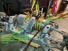
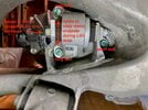
There are 3 LDU mounts and 2 tight locations to watch for clearance. Seen many removed LDUs with chipped plastic connector on the inverter side.
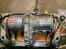
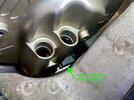
Raise the Subframe Jack instead of Dropping the LDU
Hydraulic cherry picker don't have very good control dropping the heavy LDU. Much better control raising the subframe up to the LDU. So probably more accurate to call this "raising the subframe" rather than "dropping the LDU"
Rotate the driver side subframe LDU mount so it clears the LDU motor side end plate. Very tight clearance.
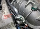
Threading in the 3 driver side subframe motor mount bolts
Need to slightly shift the heavy motor side of LDU to thread-in these bolds. Use a crow bar to help.
Drain ATF in the gearbox if haven't done so. Will need to open drain plug to check for coolant leaks.
$20 aquarium pump + 3/4" ID silicon tubing (both amazon) and 2 gallon bucket are used for coolant circuit test. Pump is silicon lubricated (says safe for fish) Ran it in the old drained coolant from LDU during removal for 5min just to clean out. Coolant circuit test ran 15min. Silicon hose crimp easily so either hold it or twist/route it for the least crimp. Pump has adjustable rate (set to ~medium) Check leak in the following areas
- Below the rotor end plate and coolant manifold (o-ringed and sealant coolant passage)
- Coolant tube on top of stator housing and its connections
- Coolant manifold drain tap
- Gearbox seam
- Bottom of inverter where it mates to the gearbox
- 2 coolant temperature sensors at 12 and 6 o'clock (they are sealed with o-rings)


Dropping the LDU back onto the Subframe
This is quite challenging as the subframe cradles the LDU tightly with little room requiring very good alignment.
Coolant inlet and passenger side subframe mount bolts
Remove the plastic coolant inlet on the manifold. Space is really tight and can easily damage this during the drop. Not sure there is even enough space for it to clear during the drop.
Locate the 3 bolts for the driver side LDU mount. Short one has < 2mm before bottoming out during assembly. If used the long one for that hole, bolt will bottom out. Put bolts aside, just remember where the short one goes.

Lifting Straps and Ratchet Location
The 2 LDU mounts in front and rear of the gearbox must be leveled for the LDU to drop into the subframe. The differential/drive shaft end of the gearbox will want to tilt downwards. Place strap ratchet on this end to adjust gearbox mount level.
Straps on motor side and inverter side probably should not cross over the gearbox to the other side under the motor mount. Can't be removed after LDU drop. Also avoid pressing the straps onto wood blocks under the subframe so an be removed.
Wach the strap's clearance to the coolant tube on top of stator housing. Avoid putting pressure on this tube by the straps. I routed tje straps underneath the tube
Thread in main bolt on driver side subframe LDU mount. Probably difficult to do so after the LDU is on the subframe


There are 3 LDU mounts and 2 tight locations to watch for clearance. Seen many removed LDUs with chipped plastic connector on the inverter side.


Raise the Subframe Jack instead of Dropping the LDU
Hydraulic cherry picker don't have very good control dropping the heavy LDU. Much better control raising the subframe up to the LDU. So probably more accurate to call this "raising the subframe" rather than "dropping the LDU"
Rotate the driver side subframe LDU mount so it clears the LDU motor side end plate. Very tight clearance.

Threading in the 3 driver side subframe motor mount bolts
Need to slightly shift the heavy motor side of LDU to thread-in these bolds. Use a crow bar to help.
Last edited:
Similar threads
- Replies
- 74
- Views
- 9K
- Replies
- 7
- Views
- 4K
- Replies
- 55
- Views
- 19K


